.png&w=384&q=75)
1. Introduction
Mechanical forming processes include a wide range of manufacturing operations conducted on metals and alloys in their solid state, i.e., without melting them. All these processes are carried out under the influence of mechanical forces using specialized equipment and devices that provide these forces and induce the desired change in the shapes or configurations of the metals and alloys [1]. Metal forming is classified into the category of deformation processes defined as deformation processes. However, some mechanical forming processes stretch the metal, others bend the metal, and others apply shear stress to the metal. Mechanical forming processes depend on the plasticity property of the metal, which is the occurrence of a permanent strain on the metal when it is exposed to external stresses, and it maintains this strain after the disappearance of this stress. This property in metals increases to a large degree when the temperature of the metals is raised. For a metal to be successfully formed, it must possess certain desirable properties, including low yield strength and high ductility. These properties are affected by temperature, ductility increases, and yield strength decreases when the forming temperature increases. Based on the effect of temperature, forming is classified into cold forming, warm forming, and hot forming, depending on the recrystallization temperature. Strain rate and friction are additional factors that affect performance in metal forming. The expansion process is divided into two categories: unsteady state and steady state, our study was conducted on the first species unsteady state expansion as shown in figure 1 [2]. Brass, a copper – zinc alloy, exhibits significant strain hardening behavior under plastic deformation. During cold working, dislocation density within the crystal structure increases, leading to a rise in flow stress and an overall enhancement in material strength. This strain hardening effect is particularly pronounced in α-phase brasses due to their face-centered cubic (FCC) structure, which allows for multiple slip systems. As deformation continues, the material becomes harder and less ductile, which may limit its formability unless followed by thermal treatments such as annealing. The degree of strain hardening in brass depends on its composition, initial grain structure, and the extent of plastic strain applied. Understanding this behavior is critical when designing forming processes to avoid premature failure or excessive work hardening [3, p. 39-47].
Investigated the pipe end forming process through an experimental approach supported by the Taguchi method. The study evaluated the effects of three primary variables: cone angle, expansion ratio (rₚ/r₀), and lubrication, each tested at three levels. The analysis revealed that the cone angle was the most influential parameter, contributing 43.56% to the overall expansion outcome [4]. The model developed using Taguchi analysis accurately predicted the radial expansion with 95% confidence, reaching a value of 56.58%, and showed good agreement with the experimental data. This indicates the model’s reliability in forecasting pipe expansion based on selected process variables [5, p. 206-214] performed an analytical and numerical investigation of the circular tube expansion process, focusing on energy absorption behavior under rigid-plastic material assumptions and various friction coefficients (µ = 0–0.3). The results showed that increasing the die half-angle reduces the contact area between the tube and die surfaces, and that small die angles with long contact lengths are inefficient for energy absorption. It was also found that at µ = 0.3, frictional energy accounted for 44.57% of the total dissipated energy. Moreover, increasing the cone angle enhanced the plastic deformation energy while reducing the frictional losses, indicating a strong relationship between geometry and energy distribution in the expansion process [6, p. 157-165] developed an analytical model for metal pipe expansion based on the principle of energy conservation, assuming a rigid–plastic material behavior and the use of a conical die. The model equates the axial compressive work to the energy dissipated by circumferential tension, longitudinal bending, and frictional resistance. A mathematical formulation was proposed to predict the required compressive force and the expanded radius, considering the effects of strain hardening (n) and friction. Model validation against previous numerical and experimental studies showed good accuracy, particularly for small die angles. It was also concluded that the expanded radius is more influenced by die and tube geometry than by material properties like strain hardening or friction [7, p. 12-22] investigated the fracture behavior in the forming of thin-walled aluminum tubes (AA6063-T6) under room temperature conditions. Tubes with an outer radius of 20 mm and a wall thickness of 2 mm were expanded using tapered conical dies with half-angles of 15°, 30°, and 45°, and slant heights of 10, 39, and 44 mm. The critical instability force (48.5 KN) was experimentally determined as the threshold for axisymmetric buckling. The study combined experimental testing, circle grid strain analysis, analytical modeling, and finite element simulations to characterize the onset of fracture and the critical ductile damage. It was concluded that fracture strains can be predicted from the measured maximum radius of the expanded tube, though direct measurements at the gauge length tend to overestimate damage due to necking and unstable crack propagation. The study emphasized the importance of combining modeling with experimental validation to accurately capture failure mechanisms in tube expansion [8, p. 1600258] investigated the determination of material constants for ductile fracture criteria in tubular materials using a conical expansion test. Two types of seamless steel tubes were tested at room temperature (23°C) with three die half-angles (10°, 15°, 30°), and a constant die velocity of 0.05 mm/s. Lubrication was applied using PTFE and organic molybdenum. The study employed both experimental tests and finite element simulations using LS-DYNA. Results showed a strong agreement between the minimum thickness obtained experimentally and that predicted by FEM. It was found that lower die angles result in greater minimum thickness, indicating that the stress – strain state significantly affects the expansion limit. Additionally, material constants for ductile fracture could be accurately derived using any two of the three die angles, as their effect on predicted expansion limits was minimal. This suggests that while different conical angles introduce varying frictional effects, the resulting material constants remain relatively consistent [9] conducted a comprehensive experimental, numerical, and analytical investigation of the tube flaring process, focusing on the influence of the outer diameter-to-thickness (OD/t) ratio. The study used SS304 stainless steel tubes with varying outer diameters and constant thickness, expanded using a 30° half-cone die. Finite element simulations were performed using ABAQUS, and the force – displacement curves were divided into four distinct stages: elastic deformation, onset of plastic bending, initial expansion, and stabilized expansion. The results demonstrated that geometrical parameters such as die angle, outer diameter, and tube length significantly affect the expansion behavior and the material's resistance. The study emphasized the importance of dimensional ratios in governing deformation mechanisms and load response during tube flaring. The primary objective of this research is to systematically investigate the mechanical behavior of cold expansion in BR6040 brass tubes by examining the combined effects of wall thickness (1.8 mm and 2.6 mm) and die semi-angle (15°, 20°, and 30°). The study aims to experimentally characterize the influence of these geometric parameters on forming load, deformation capacity, and fracture initiation, while also validating the findings through numerical simulations. This research seeks to fill existing gaps in understanding how variations in thickness and die angle affect the cold forming process of these alloys, providing practical insights for optimizing industrial tube expansion operations.
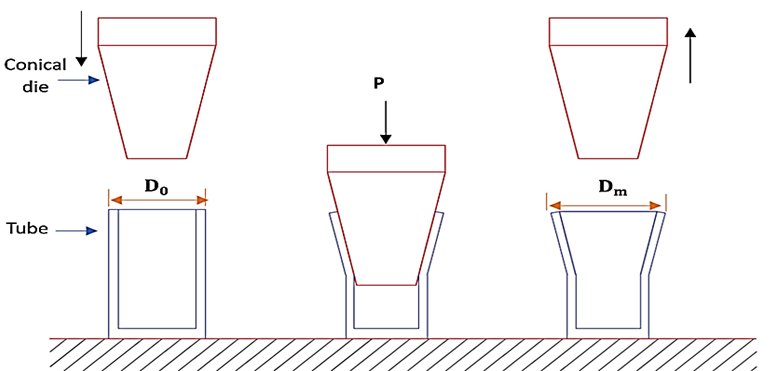
Fig. 1. Un-steady state of tube end expansion
2. Numerical Analysis
To support and validate the experimental results, numerical simulations were performed using Abaqus, a robust finite element analysis software widely used for modeling metal forming processes. The simulations replicated the cold expansion of BR6040 brass tubes under varying wall thicknesses and die semi-angles. A detailed model was created to represent the tubular specimen and the conical die, as shown in figure 2 which illustrates the geometry and boundary conditions applied in Abaqus. Material properties mechanical parameters, including elastic modulus, Poisson’s ratio, density, yield stress, and hardening behavior, were input based on experimental data. The coefficient of friction between the tube’s inner surface and the die was set to 0.12, a value selected based on the close agreement observed between simulation predictions and experimental load – displacement curves. This friction value reflects the effect of lubrication applied during experiments and helps ensure realistic contact interactions within the model.
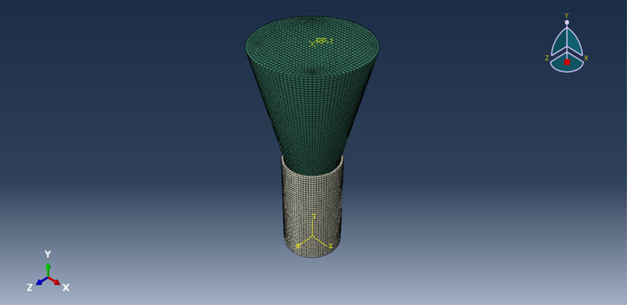
Fig. 2. FE model for tube end expansion
3. Experimental Part
The experimental part of this study focuses on the cold expansion process of metallic tubes made from BR6040 brass. Two wall thicknesses (1.8 mm and 2.6 mm) and three die semi-angles (15°, 20°, and 30°) were selected as the primary geometric variables to investigate their effect on the forming behavior. Prior to testing, all specimens – both expansion and tensile samples – underwent annealing heat treatment to eliminate residual stresses and improve ductility. The brass specimens at 550 °C, held for one hour, followed by furnace cooling figure 3 shows the tensile test setup used to characterize the mechanical behavior of brass alloys under cold conditions. These inputs are summarized in table 1, presenting the key parameters for brass alloys used in the simulations. Figure 4 illustrates the geometry and dimensions of the tubular specimens, while table 2 summarizes the sample dimensions for both materials. Figure 5 shows the actual specimens used in this research, and figure 6 presents the conical dies with varying semi-angles used in both the experimental and numerical stages. All tests were performed using a Microcomputer-Controlled Electronic Universal Testing Machine (100 KN) at a constant punch speed of 1 mm/min, ensuring consistency across all trials.
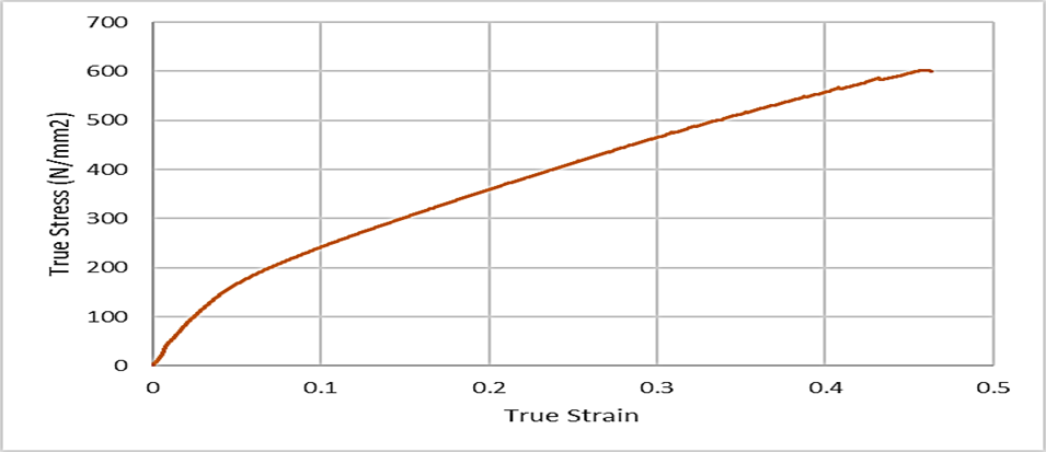
Fig. 3. True stress and True strain curve for brass alloy
Table 1
Properties for brass 6040 at cold forming
Properties | BR6040 |
Young Modulus (E) | 100 GPa |
Yield stresses ( | 144.3016 MPa |
Strain hardening (n) | 0.5881 |
Poisson ratio | 0.33 |
Density | 8.201 g/cm3 |
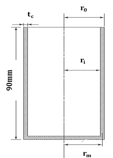
Fig. 4. General geometric shape of thickness
Table 2
Dimensions of the samples for each thickness
tc | ri | ro | rm |
1.8 mm | 14 mm | 15.8 mm | 14.9 mm |
2.6 mm | 14 mm | 16.8 mm | 15.3 mm |
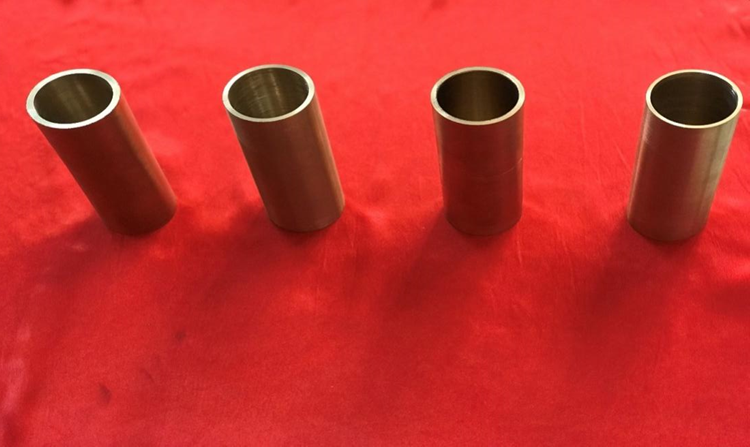
Fig. 5. Manufactured expansion samples
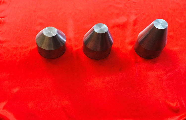
Fig. 6. Represents the different shaping dies
4. Results and discussion
This section presents and discusses the experimental results of the cold tube expansion process applied to BR6040 brass specimens under varying wall thicknesses (1.8 mm and 2.6 mm) and die semi-angles (15°, 20°, and 30°). The load–displacement curves obtained from the cold forming tests are analyzed to evaluate the influence of geometrical parameters on the material behavior, forming load, and deformation characteristics. Furthermore, the effect of increasing wall thickness and die angle is examined in detail, highlighting their impact on the required forming force and failure modes. The discussion also considers the trends observed in light of material properties and forming mechanics.
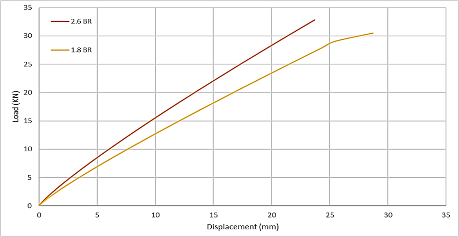
Fig. 7. Experimental Load- Displacement of BR6040 at angle (15°)
Figure 7 shows Experimental the load-displacement curves for brass at 15° and for various thicknesses (1.8, and 2.6 mm). The curves show a gradual increase in load with increasing displacement until a peak is reached, followed by a sharp or gradual decrease depending on the forming type. In cold forming, the curves showed a sharp increase in load to a maximum value, followed by a sudden drop caused by fracture or sudden collapse of the material. The increase in thickness led to an increase in the maximum load in both cases, as greater thickness provides greater resistance to deformation due to increased mechanical hardness and cross-sectional area. The decrease in load in hot forming was evident for all thicknesses due to the effect of temperature on reducing the resistance of the brass and stimulating intergranular sliding, reducing the need for a large load to achieve the same displacement.
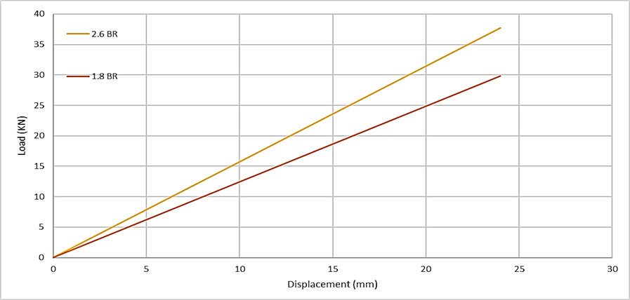
Fig. 8. Experimental Load- Displacement of BR6040 at angle (20°)
Figure 8 shows Experimental the load–displacement curves of brass metal at 20° for four thicknesses (1.8, and 2.6 mm) for cold forming. The curves show a gradual increase in load with displacement until a peak is reached, followed by a sharp or gradual decrease, depending on the forming condition, just as at the previous angle, but with different dynamic behavior due to the change in contact angle. In cold forming, the curves showed a sharp rise in load, peaking at 2.6 mm thickness with a load exceeding 37.68 KN, followed by sudden collapse in almost cases. This increased die angle results in increased friction due to the contact length, which explains the need for higher loads in some cases, especially with high thicknesses. Continuing with what was observed at the 15° angle, increasing thickness increases the resistance to deformation, thus increasing the maximum load value. The 2.6 mm thickness recorded the highest load value in cold forming, indicating maximum resistance to axial stress in the contact area.
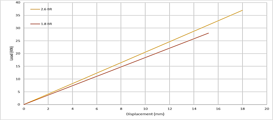
Fig. 9. Experimental Load- Displacement of BR6040 at angle (30°)
It is noted from figure 9 Experimental that increasing thickness leads to a significant increase in the load required for expansion in cold forming. Larger thicknesses provide greater resistance to deformation due to the increased material and resistance to deformation, which explains the higher load requirement. The curve (2.6 BR 30 cold) has the highest maximum load but the lowest ductility.
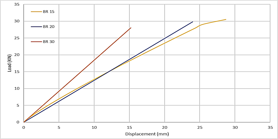
Fig. 10. Experimental Load-Expansion Ratio of BR6040 at thickness (1.8 mm)
In cold forming, the load gradually increases with increasing angle, reaching its highest value at 30°, reflecting the need for greater deformation energy due to the material's greater resistance to expansion. This behavior is expected due to the increased geometric impedance with increasing angle. On the other hand, the plastic strain was more pronounced at 20° compared to 15°, indicating a balance between load and deformation; the load then increases sharply at 30°, with fracture occurring at a relatively lower displacement. Increasing the die angle inherently raises the frictional forces and flow resistance at the die – tubular interface, which contributes to a reduction in material displacement during forming. At a thickness of 1.8 mm, the 20° angle appears to offer a relatively balanced behavior, providing an optimal compromise between formability and mechanical resistance. In cold forming, the 30° angle enables the highest expansion force, making it suitable for applications requiring maximum material deformation.
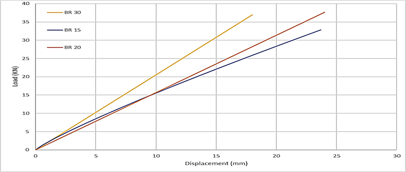
Fig. 11. Experimental Load- Expansion Ratio of BR6040 at thickness (2.6 mm)
In figure 11, Experimental for BR6040 at constant thickness (2.6 mm), for different conical die angles, and for cold forming. At the die angle (![]() ), observe a gradual upward curve, indicating good stress distribution and a more "flowy" formation, the higher displacement before fracture allows the material to withstand greater expansion without failure. The maximum load is relatively low because the forces are distributed over a wider area and stress concentration is reduced. This is the best angle for achieving large plastic deformation, but it requires a longer time to reach full expansion. At angle (
), observe a gradual upward curve, indicating good stress distribution and a more "flowy" formation, the higher displacement before fracture allows the material to withstand greater expansion without failure. The maximum load is relatively low because the forces are distributed over a wider area and stress concentration is reduced. This is the best angle for achieving large plastic deformation, but it requires a longer time to reach full expansion. At angle (![]() ), it exhibits a load greater than 15°, with a slight decrease in displacement and a more stable behavior before fracture, indicating a balance between strength and ductility. This is ideal if the aim is to reduce forming time without losing tubular ductility. At angle (
), it exhibits a load greater than 15°, with a slight decrease in displacement and a more stable behavior before fracture, indicating a balance between strength and ductility. This is ideal if the aim is to reduce forming time without losing tubular ductility. At angle (![]() ), the highest load is required to achieve the desired expansion. Fracture occurs at a low displacement, indicating a sudden fracture, often due to stress concentration. It is characterized by a sharp behavior after the maximum load, indicating sudden failure and poor formability. This angle is not ideal for cold forming operations, although it reduces forming time.
), the highest load is required to achieve the desired expansion. Fracture occurs at a low displacement, indicating a sudden fracture, often due to stress concentration. It is characterized by a sharp behavior after the maximum load, indicating sudden failure and poor formability. This angle is not ideal for cold forming operations, although it reduces forming time.
5. Conclusions:
- Forming load increases with die angle at a given displacement, while smaller angles enable greater expansion before failure.
- Thicker tubes (2.6 mm) required higher forming loads compared to thinner ones (1.8 mm), regardless of material or die angle.
- BR6040 brass demonstrated superior formability and ductility in all tested configurations.
- The interaction between wall thickness and die angle strongly influences both the maximum load and the extent of deformation.
- Finite element analysis using Abaqus predicted the forming behavior with acceptable accuracy, supporting the validity of the experimental observations.
- The combined experimental and numerical results offer practical insights for optimizing cold tube expansion processes based on material type and geometric design.
