.png&w=384&q=75)
Introduction
A heat exchanger will be easier to transfer heat if the heat transfer fluid with higher temperature and pressure values is directed inside the tubes. In the first case, this allows for the use of high-purity, high-alloy steels only for the tube grid, while the casing can be made from simpler materials. In the second case, it facilitates the cleaning of the tubes during the operation of the heat exchangers. Typically, the media that are subject to pressure loss limitations (which are usually gaseous media with lower pressures) are more conveniently placed outside the tubes. By adjusting the spacing of the tubes in the bundle and the number of passes in the intertube space, it is possible to maintain the desired pressure loss.
If one of the heat carriers evaporates or condenses, it is more convenient to direct it into the intertubular space, otherwise there is usually an uneven distribution of the heat carrier flow through the pipes and a decrease in the efficiency of the apparatus.
Despite the variety of heat exchangers used, it is possible to briefly formulate the main requirements for them in terms of thermal, hydrodynamic, structural, operational, and technological characteristics: maximum compactness, i.e., the device has a low weight and dimensions for a given value of thermal capacity and capacity for pumping heat carriers.
The decision on which heat carrier should be sent inside the pipes and which outside depends on the pressure and temperature of the media, the convenience of the apparatus layout in the technological scheme in which it operates, the aggressiveness of the heat carrier and the heat exchange surface that it contaminates, and the allowable pressure loss in the heat carrier. Of all the existing types of recuperative apparatuses, the plate-and-fin apparatuses are the most compact, allowing up to 1,500 m2 of heat exchange surface to be accommodated in 1 m3 of apparatus volume. The housings of such devices are usually rectangular, which prevents their use at high temperatures and pressures of heat carriers.
One of the types of tubular apparatuses are tubular-ribbed. They are used in cases where the heat transfer coefficient outside the pipes is many times less than the heat transfer coefficient inside the pipes. Increasing the heat exchange surface outside the pipes and additional flow turbulence by the ribs allow to significantly increase the heat removal from the surface of the heat exchange pipes.
There are several ways to improve the thermal and hydrodynamic characteristics of heating surfaces, one of which is to develop the inner and outer surfaces of the pipes by radially indenting sections of the pipe wall to create depressions and protrusions of various profiles (fig. 1)
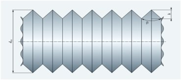
Fig. 1. Surface diagram of a heat exchanger with triangular annular depressions and protrusions [1, p. 47-52]
Increasing the surface area of the heat exchange apparatus allows for significant development of the surfaces that are exposed to heat carriers inside and outside, as well as for intensifying heat exchange by turbulizing the flows in the recesses and depressions.
If we approximate the surface profile as a sequence of triangular protrusions and depressions and neglect the thickness of the shell, a simple geometric analysis shows that the degree of development of the channel surface ψ = Ftr/Fgl depends on the angle at the apex of the triangular protrusion β (0 < β < π) and its height h:
 , (1)
, (1)
where Ftr is the surface area of a pipe with triangular protrusions and depressions; Fgl is the surface area of a smooth pipe. The function y = 1/sin(β/2) is minimal (equal to 1) at β = π and tends to infinity at β → 0. By reducing the angle β, a significant increase in the heat exchange surface can be obtained. So, if we take the profile of the protrusion in the form of an isosceles triangle with a right angle at the vertex β = π/2, then the degree of surface development will be:
![]() , (2)
, (2)
It follows that the maximum (ultimate) degree of surface development, equal to ψpred = √ 2, is achieved when h → 0, when the number of protrusions per unit length of the pipe tends to infinity. If an equilateral triangle (β = π/3) is taken as the basis, then formula (1) becomes:
![]() , (3)
, (3)
It is possible to obtain a surface development degree of ψ > 2 by further reducing the angle β. In this case, the profile of the outer and inner surfaces corresponds to the profile of a cross-finned pipe, where the heat exchange conditions on the inner and outer surfaces are significantly deteriorated, indicating that it is not advisable to reduce the angle β indefinitely.
If we represent the surface profile as a sequence of semicircular protrusions and depressions (fig. 2) and neglect the thickness of the shell, we can show that the degree of surface development of the channel, ψ, depends only on the diameter of the semicircular protrusion:
![]() , (4)
, (4)
In case (4), the maximum degree of surface development, equal to ψpred = π/2, is achieved when d → 0, when the number of protrusions per unit length of the pipe tends to infinity. Any significant (ψ > 1.15) two-sided surface development is advantageous, as it directly affects the increase in the transferred heat flux and ensures a corresponding reduction in the metal consumption of the heat exchanger.
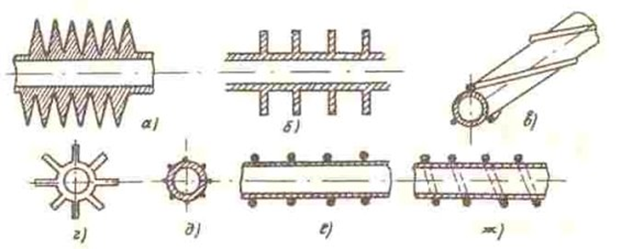
Fig. 2. Design of heat exchange tubes with a developed heat exchange surface [1, p. 47-52]: a – transverse helical fins; b – transverse annular fins; c – spiral fins; d – longitudinal fins; e – fins made of longitudinally welded wires; f, g – wire fins: annular or spiral
The presence of fins on the outer surface of the pipes increases the spacing of the pipes in the bundle and changes the assembly technology of tubular apparatuses.
The presence of finning on the outer surface of tubes requires increasing the tube spacing in the bundle and changes the assembly technology of tubular apparatuses.
Intensification of heat exchange in tubes allows reducing mineral deposits on the inner surface by approximately five times compared to smooth round tubes. In this regard, the class of spring-wound channels proposed by scientists is of practical interest, the coils of which are made of wire of various cross-sections and rigidly fastened by laser welding. Figure 3 shows a spring-wound channel made of round cross-section wire.
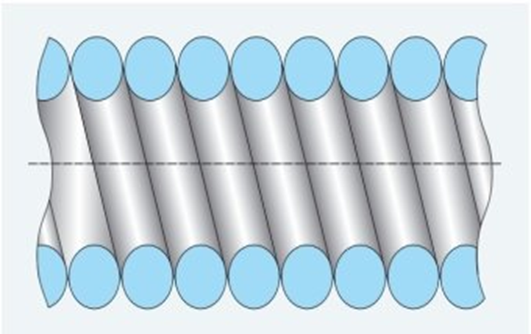
Fig. 3. Diagram of spring-wound channel [1, p. 47-52]
The degree of surface development ψ of spring-wound channels is determined by expressions (1) and (2). Unlike cylindrical channels, the configuration of spring-wound tubes ensures a reduction in metal consumption compared to a smooth channel by an average of 27%.
Indeed, the ratio of the mass of material required for manufacturing tubes of equal length equals the ratio of cross-sectional areas of these channels [1, p. 47-52].
Thus, for example, for a spring-wound channel made of round cross-section wire, the ratio is:
![]() , (5)
, (5)
Where Mgl is the mass of a smooth tube; Mkr is the mass of a spring-wound channel made of round cross-section; S is the cross-sectional area of the wall of a smooth tube Sgl and spring-wound channel Skr, respectively. To intensify heat exchange through flow turbulization, it is proposed to install intensifiers 2 in the flow part of heat exchange element 1, made in the form of spiral spring-wound elements rigidly fixed between the coils of a tight spring (fig. 3).
In connection with the development and use of nanotechnologies in the production process, there is a possibility of manufacturing such tubes from non-ferrous metals (aluminum, brass, copper).
For a heat exchange surface element dF, the heat transfer equation in differential form is written as:
![]() , (6)
, (6)
Where K is the heat transfer coefficient, W/(m²·K); ΔT = TH - TC is the current temperature difference. The total heat flux through the heat exchange surface:
![]() , (7)
, (7)
To determine Q, it is necessary to know the distribution of K and ΔT over the heat exchange surface. For single-phase heat carriers, the heat transfer coefficient usually changes insignificantly and therefore is taken as constant over the entire heat exchange surface. Then:
![]() , (8)
, (8)
Where the average temperature difference over the heat exchange surface:
![]() , (9)
, (9)
Equation (8) is the heat transfer equation. It allows determining the heat exchange surface F in design calculations.
If in a heat exchanger the heat transfer coefficient changes significantly in certain sections of the heat exchange surface (as, for example, in apparatuses with boiling or condensation of heat carrier on part of the surface), an average coefficient K over the surface is introduced [3].
For a flat wall, the heat transfer coefficient:
![]() , (10)
, (10)
Where α₁, α₂ are heat transfer coefficients, W/(m²·K); δ is wall thickness; λ is thermal conductivity coefficient of wall material, W/(m·K).
For a cylindrical wall, when relating heat flux to internal and external surfaces respectively:
![]() , (11)
, (11)
![]() , (12)
, (12)
Where α₁, α₂ are heat transfer coefficients inside and outside the tube, W/(m²·K); d₁ and d₂ are internal and external diameters.
If d₂/d₁ ≤ 1.8, then the use of determination of K by the formula for a flat wall (10) is quite acceptable, i.e.:
![]() , (13)
, (13)
Where d₀ = d₁ when α₁ >> α₂; d₀ = d₂ when α₂ >> α₁; d₀ = 0.5(d₁ + d₂) when α₁ ≈ α₂; here L is tube length.
If we introduce a linear heat transfer coefficient for a cylindrical wall:
![]() , (14)
, (14)
Then:
![]() , (15)
, (15)
The calculated dependencies necessary for determining heat transfer coefficients are given in textbooks, monographs, and reference books, for example in [4].
Reference [4] provides recommendations for calculating heat transfer in tubes, annular and flat channels, and longitudinally washed tube bundles.
Heat exchangers also use cross-flow bundles of smooth tubes with staggered and in-line arrangements. Average heat transfer for multi-row bundles of smooth tubes (Z > 10) is determined by the formula [4]:
![]() , (16)
, (16)
Where for in-line bundles at Re = 10³...2×10⁵, the coefficients are C = 0.56 and n = 0.5; at Re = 2×10⁵...2×10⁶, C = 0.2 and n = 0.65 for S₂/d ≥ 2, and C = 0.2(S₂/d)^0.2, n = 0.65 for S₂/d < 2; for S₂/d ≤ 1.5, C = 0.2 is taken; for S₂/d > 3, S₂/d = 3 is taken. At Re > 2×10⁶, coefficients are C = 0.02, n = 0.84. For staggered bundles at Re = 10³...10⁵, C = 0.64, n = 0.5; at Re = 10⁵...2×10⁶, coefficients are C = 0.23 + 0.06/(S₁/d - 1), n = 0.6; at Re > 2×10⁵, coefficients are C = 0.023, n = 0.84.
Thus, the outer tube diameter DH is taken as the defining dimension, the average velocity in the narrow cross-section of the bundle as the design flow velocity, the average flow temperature as the defining temperature, and the Prandtl number Prw is determined by the average wall temperature. For gases, Prf/Prw = 1.
