Introduction. Analysis of known approaches to the automatic landing task of PUA
The entry mode for landing and direct landing is the most complex and tense mode of all flight modes of aircraft (UA). This is primarily due to the high speed of the descent process and the high degree of crash of the UA in this mode due to the very high neuropsychological load of the crew. This mode has a fairly high frequency and requires the crew to be confident, coherent, and quick to react to changes. Landing and landing time does not exceed 1-2% of the flight time, but under this mode, this percentage is 50% of all aviation accidents (AH). This regime accounts for 55% of all losses over the past 40 years. Difficulty driving under poor visual conditions (fog, darkness) increases especially when visual orientation is difficult or impossible [1].
Implementing the automatic descent of the UA, which is quite relevant for PUA, is a more complicated task. In this case, the aircraft deck control system should address the issues of action planning, assessment of the current situation and management of the executive bodies instead of the pilot. In this case, the control system (IS) must ensure stability, short-term operation of large deviations, adaptability to the effects of deviations and accuracy of access to a certain point of departure.
The formula for calculating the control signal during the course control of the UAV
When the PUA is at a distance from the aerodrome, the control point on the UEZ axis len and the angle of rotation Ψp can be used to determine the direction of rotation and passage with the sign 00, as the "descent" signal can be received from the ground control point. additional computational operations are required. In this case, the effect of wind may not be taken into account.
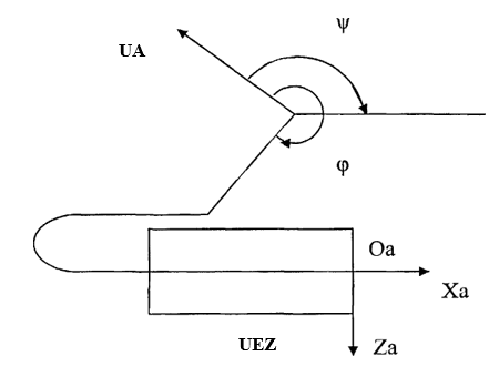
Fig. 1. UA course management scheme
The formulas for calculating the deflection angle and control signal to the bending channel are given below:

when, k1 = 4, k2 = 2, k3 = 1,
Ψp calculated according to the following formula:

m = φ + Ψ – Ψa , (1.3)
Ψ – the angle of the plane (the angle between the PUA axis and the magnetic needle, here); Ψa – UEZ course angle.
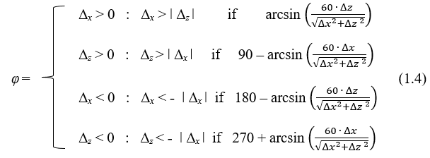
when, Δx = x - xa , Δz = z - za These are PUA coordinates.
It is clear that the application of formulas (1.1 - 1.4) on the PUA deck requires the creation of a special program for the Digital Computing Machine (GRHM) on board. Instead, it is proposed to replace time-consuming operations for calculating trigonometric functions with an easily applied neural network (NN) based on a Programmable Logical Integrated Scheme (PMIS).
Assess the feasibility of neural network application with PMIS on the course of the PUA control channel.
According to the calculation formulas 1.1 - 1.4 given in the previous paragraph, the research samples of the neural network presented in Tables 1, 2, 3 on APPENDIX 2 were compiled. In total, 214 samples were used for 3 alternative deviations of PUA electrons upon return to the landing area.
Based on 214 samples, the following characteristic neural network was created and studied in the MATLAB environment: Neural network type: multipoint neural network for direct propagation.
Input neurons: 5.
- Output neurons: 3 (j = 1, j = 2, j = 3 corresponds to the number of alternatives).
- Secretory layer neurons: 5. Neurons in the second secretory layer: 2.
- The activation function of the latent layers - sigmoid, the output layer - linear.
- Number of research periods: 200.
- Research method - the method of error redistribution.
Figure 2 shows the block diagram of the neural network.
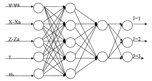
Fig. 2. Structural scheme of neural network
Figure 3-6 presents a neural network scheme developed in MATLAB SIMULINK.
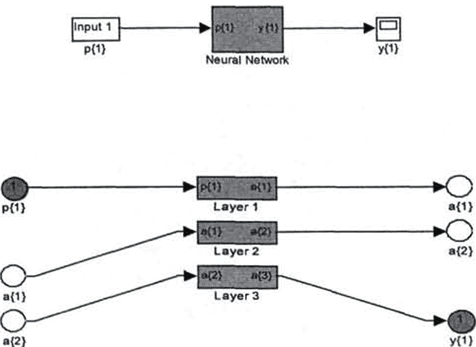
Fig. 3. Neural network scheme developed on MATLAB SIMULINK
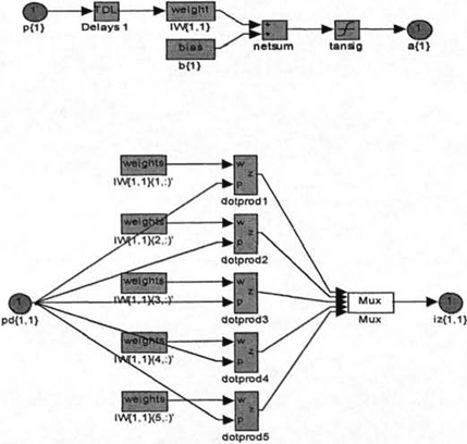
Fig. 4. The first layer of the neural network
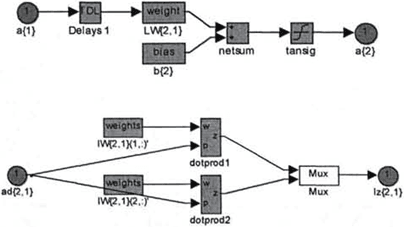
Fig. 5. The second layer of the neural network
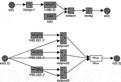
Fig. 6. The third layer of the neural network
Figure 7 provides a graph of the error change depending on the number of study cycles performed.
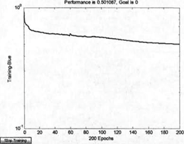
Fig. 7. Error change schedule depending on the number of research cycles performed
It is possible to make assumptions about the quality of neural network research based on errors of 0.5 or 190 on 214 alternatives selected correctly.
As a result of the study, the following indicators on weight coefficients and displacement were obtained:
Weight ratio for the first layer:>>net.IW {1,1}
ans=

Displacement for the first floor:
>>net.b {1}
ans=
2.7464
-0.3714
-0.5267
0.6961
-2.5634
Weight ratios for the second layer:
>>net.LW {2,1}
ans=

Displacement for the second floor:
>>net.b {2}
ans=
-1.7332
1.6243
Weight ratios for the third layer:
>>net.LW {3,2}
ans=

Displacement for the third floor:
>>net.b {3}
ans=
-2.1709
-0.0938
-2.3232
3.3. Results
- It has been determined that the calculation of the control signal during the PUA course and the free angles of the diaper over the control point on the UEZ axis is related to time-consuming trigonometric calculations.
- A three-layer neural network structure consisting of 13 neurons, which is easily applied by PMIS for course control during the return of the UAV to the landing site, has been developed and studied to significantly reduce time consumption.
- Semi-natural modeling confirmed the results of analytical calculations.

.png&w=640&q=75)