
Implants for rehabilitation and retention of dental and facial prostheses have graduated from a phase of wishful thinking to one of the most gratifying experiences for patients and treating fraternity alike. This magnificent journey began about 3000 years ago, when a copper stud was nailed into an Egyptian’s mouth. This was documented by Dr and Mrs Popenoe, after their excavations in 1931 in Honduras. They found a mandible of Mayan skull with tooth shaped pieces of shells in the sockets of missing teeth. In the recent history Magiolo (1809), Edmunds (1886) and Harns (1887) attempted similar things using a variety of metals in different shapes after a certain period of post extraction healing.
Dahl (1940) proposed intramucosal implants or button implants. The subperiosteal implants were suggested in 1941.
There was a period of lull in the implant activity all over the world till 1952, when Bränemark demonstrated that under controlled conditions titanium could be. Structurally integrated into living bone with a high degree of predictability of success. Thereafter, the expedition moved to Linkow’s bladevent implants (1967) followed by Robert and Roberts, ramus frame implants (1970). The first screw shaped implant, however, was placed in a patient in 1965.
Bränemark coined the term “Osseointegration” which has, probably been, derived from Latin ‘Os’ (meaning ‘bone’) and integration (meaning ‘being contained’).
Osseointegration as defined by Bränemark and coworkers (1989) is “total integration of an implant in bone” specially after the bone is healing after trauma of implant placement in bone. Osseointegration logically, should be better known as Osteointegration. This phenomenon has also been called as “ankylotic bond”.
Implant Materials
Many metals and non-metals have been used as implants materials. These could broadly be classified as:
Metal and alloys:
- Titanium (Pure) 100% pure (cpTi)
- Titanium alloy Titanium 90% Chromium 2%
- Molybdenum 7%, Chromium cobalt Cobalt 66% alloy Chromium 37%
- Stainless steel Iron 70% Chromium 18% Nickel 12%
- Tantalum 100% Pure
- Zirconium 100% Pure
- Gold 100% Pure
- Platinum 100% Pure
Inert ceramics
- Polycrystalline
- Single crystal
- Zirconium oxide ZrO2 Zircona
- Titanium oxide TiO2
Bioactive and biodegradable ceramics:
- HydroxyapatiteCa10(PO4)6(OH)2
- Tricalcium phosphate Ca 3(PO4)2
- BioglassCaPO4
- Calcium aluminates
- Carbon
- Carbon silicone
- Polycrystalline glassy carbon
Polymers:
- Polymethylmethacrylate
- Polytetra fluoroethylene
- Polyethylene
- Polyethylene terephthalate
- Polypropylene
- Siliconrubber
- Polysulfone
Out of the above, pure titanium is highly reactive, but when it comes in contact with air or body fluids, becomes ‘titanium oxide’, which is probably the most bio inert. Pure titanium, when exposed to environment. quickly undergoes oxidation and forms a thin layer (5 to 20 m thick) of titanium oxide, this titanium oxide is almost totally inert. Even this metal is considered to release some amount of titanium in the patient’s body.
This titanium ‘load’ is considerably less (about 10,000 times as per rough estimates) than the total ingestion of titanium via various foods. Therefore, it will be seen that this ‘release’ appears to be non-significant. Furthermore, the biologic half life of titanium is 320 days far too short to accumulate in human body to any levels of clinical importance. Titanium, in its implanted, form offers considerable strength (both crushing and shearing) to with stand the occlusal or functional load, that would be put on the final prosthesis ultimately. This coupled with Osteointegration makes it, so far, the closest to ideal implants materials.
Titanium Implants
These are either ‘plasma coated’ or are surface ‘etched’ (by sand blasting or LASER) to further help in Osteointegration, but the rough surface of the implant, so prepared is unsuitable for soft tissue (gingival cuff) and leads to inflammation in the gingiva, much in the same way as the plaque and calculus on the natural teeth. To overcome this difficulty the neck of the implant (the portion which is above the alveolar crest of bone but is encompassed by the gingiva) is highly polished which obviates gingival irritation and ensures a healthy interface between implants and the gingiva.
Classifications of Dental Implants
Based on Shape and Form
- Post or root form implants
- Solid tapering types
- Solid cylinder type
- Pin types
- Screw shaped implant type
- Basket design
- Hollow cylinder design
Blade implants
- Conventional blade design
- Vented blade design
Based on Surface Characteristics
- Titanium plasma – Sprayed coating
- Sand blasting – Surface etching
- Laser induced surface roughening
- Hydroxyapatite coating
Based on Implant Tissue Interface
- Osseointegration
- Fibrointegration
Based on Foundation
- Implant supported
- Implant assisted
Based on Mode of Retention of Prosthesis
- Removable
- Fixed
- Screw retained
- Cement retained
Based on Various Systems
- Branemark implant system (Nobel Biocare System)
- International Team for oral Implant (ITI) System
- Implant Innovations system d. Astra Dental Implant System
- IMZ implant system (InterporeIMZ)
- Coreventsystem
- Sterri-OssSystem
- Endosteal Hollow BasketSystem
Immediate Implants
Immediate implants are those which are inserted into the freshly extracted teeth sockets.
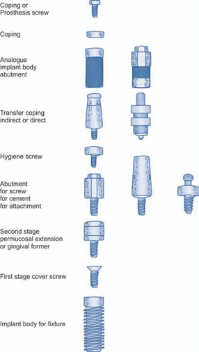
Fig. 1. Schematic diagram of generic implant components and terminology developed by C.E. Misch and C.M. Misch
Transient Implants for Immediate Loading. As the name suggests these are temporary and are suitable to carry prostheses during the period of Osteointegration of regular Implants.
Parts of Implant
A generic language for endosteal implants has been developed by Misch and Misch. It is presented in an order following the chronology of insertion and restoration. In formulating the terminology, five commonly used systems were referenced.
The endosteal implants have segmented portions placed in different phases. At the time of insertion of the implant bod y or first stage surgery, a cover is placed into the top of implant to prevent bone, soft tissue, or debris from invading the abutment connection area during healing. If the first stage cover is screwed into place, the term cover screw is used (fig. 1). After a prescribed healing period sufficient to allow a supporting interface to develop, a second stage procedure may be performed to expose the implants and / or attach a transepithelial portion. This transepithelial portion is termed as permucosal extension or gingival former, because it extends the implant above the soft tissue and results in the development of a permucosal seal around the implant. This implant component is also called a healing cap. Another name given to this implant component is healing abutment, because in stage II to uncover implant, often this device is used for initial soft tissue healing.
The abutment is the portion of the implant that supports and/ or retains prosthesis or implant superstructure. A superstructure is defined as a metal framework that fits the implant abutment (s) and provides retention for a fixed prosthesis. Three main categories of implant abutment are described, according to the method by which the prosthesis or superstructure is retained to the abutment.
- An abutment for screw retention uses a screw to retain the prosthesis or superstructure.
- An abutment for cement retention uses dental cement to retain the prosthesis or superstructure.
- An abutment for attachment uses an attachment device to retain a removable prosthesis. The prosthesis may be classified as fixed, whenever cement retains the prostheses, fixed/ removable when screws retain a fixed prosthesis and removable when the prosthesis is removed by the patient. Each of the three abutment types may be further classified as straight or angled abutments, describing the axial relationship between the implant body and the abutment (fig. 2-3). An abutment for screw retention uses a hygiene cover screw placed over the abutment to prevent debris and calculus from invading the internally threaded portion of the abutment during prosthesis fabrication. An impression is necessary to transfer the position and design of the implant or abutment to a master cast for prosthesis fabrication. A transfer coping is used in traditional prosthesis to position a die in air impression. Most implant manufactures use the terms transfer and/ or coping to describe the component used for the final impression. Therefore a transfer coping is used to position an analogue in an impression and is defined by the portion of the implant it transfers to the master cast, either the implant bod y transfer coping or the abutment transfer coping. Two basic implant restorative techniques are used to make a master impression and each uses a different.
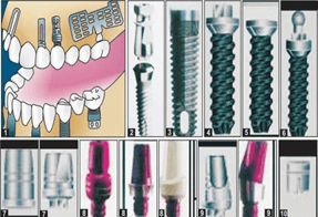
Fig. 2. (1) Different forms and shapes of implant, (2) One stage implant, (3) Two stage implant, (4) External Hex implant, (5) Internal Hex implant, (6) Ball and socket implant, (7) External straight Hex abutment, (8) Internal straight Hex abutment, (9) Internal angulated hex abutment, (10) Abutment for ball and socket implant
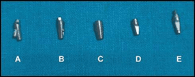
Fig. 3. Different forms of abutments: (A and B) Screw abutment (C) External hexagon abutment (D and E)
Angulated abutment design transfer coping, based on the transfer technique performed. An indirect transfer coping uses the impression material requiring elastic properties. The indirect transfer coping is screwed into the abutment or implant body and remains in place when the set impression is removed from the mouth. The indirect transfer coping is parallel-sided or slightly tapered to allow Ease in removal of the impression and often has flat sides or smooth undercuts to facilitate reorientation in the impression after it is removed. A direct transfer coping usually consists of a hollow transfer component, often square, and a long central screw to secure it to the abutment of implant body. After the impression material is set, the direct transfer coping screw is unthreaded to allow removal of the impression from the mouth. Direct transfer coping takes advantage of impression materials having rigid properties and eliminates the error of permanent deformation because it remains within the impression until the master model is poured and separated. An analogue is something that is analogous or similar to something else. An implant analogue is used in the fabrication of the master cast to replicate the retentive portion of the implant bod y or abutment (implant body analogue, implant abutment analogue). After the master cast obtained, the corresponding analogue (e.g. implant body, abutment for screw) is attached to the transfer coping and the assembly is poured in stone to fabricate the master cast. A prosthetic coping is a thin covering, usually design to fit the implant abutment for screw retention and serve as the connection between the abutment and the prosthesis as superstructure. A prefabricated coping is a metal component machined precisely to fit the abutment.
Biologic Parameters for Implants Acceptance
The parameters that are considered for evaluation of Implant viz a viz its success:
Material Biocompatibility
The implant material should be biocompatible (as discussed earlier) and in this category titanium screws score over all other materials for making an implant.
Implant Design
Various designs have been employed with varying degrees of success. We already know that at present the most suitable design is that of a cylinder. This has further been improved to make it a screw and then on to tapering screw implant. But then there is yet another cylindrical implant which has small spheroids attached to the surface, which not only facilitates Osteointegration by making it rough, but also increases the surface area of bone to implant contact. This is classically seen in ‘endopore’ implants. These implants are screwed into the drill hole in the bone but have to tapped into it for tight fit.
Of the screw type cylindrical implants the bone has to be either ‘tapped’ prior to implant insertion or the other variety are self-tapping types, which cut the thread in the bone as it is inserted into the bone.
Implant Surface
The surface (that part which is in the bone) has to be made ‘rough’ by either plasma spraying or surface etching also spheroids can be attached on to the surface as mentioned above. That part of implant which is above the bone level but within the soft tissue is also known as neck of the implant and therefore has to be highly polished to prevent soft tissue inflammation, so as to promote water tight gingival cuff.
Host Site
The host site plays an important role in the ultimate success of implant as quality of bone is of paramount importance for Osteointegration, e.g. if the bone is dense, then primary stability of implant would be achieved but long-term stability (achieved by Osteointegration) may not be forthcoming easily and may take longer time.
Indications and Contraindications
The implants have a very wide range of indications to their use. They may be employed to provide and retain
single tooth replacements to a few teeth as implant supported bridges as also for providing complete denture prostheses in either or both the jaws. Apart from this, the titanium implants have also been used for other applications like craniofacial implants (for retaining maxillofacial prosthesis) and in orthodontic treatment for skeletal anchorage (micro or mini implants). As regards contraindications, it can be safely said that there are no specific absolute contraindications. The implants may be inserted in any jaw except the patient who is still in growing stages (i.e. prepuberty) but then it is a relative contraindication. It would be prudent, in debilitating systemic disease, to control the condition and maintain the patient in as optimal health as is possible, a good example would be diabetes mellitus.
However, the radiated bone for cancer treatment would not be a good site for implant success.
The shape and type of jaw bones, their relationship with inferior alveolar nerve as in severely atrophied, alveolar ridges, where the inferior dental canal becomes very close to the alveolar crest; similarly in maxillary arch, the proximity of maxillary sinus and also in some cases the relative height of alveolus in relation to pyriform fossa should be kept in mind. In all such cases appropriate implant sizes (length) should be used. Sometimes, in these cases procedures like ‘sinus lift for maxilla; or alveolar bone graft for the mandible may be undertaken. Lately bone alternatives like hydroxyapatite and lyophilized bone may be considered, but autogenous bone graft still remains the choice of graft material. When selecting a small length of implant, it is advisable to select an implant of widest circumference that the recipient bone would accept. Thereby increasing the so important surface area contact of bone to implant. The rule of thumb is to select the largest implant size that would be suitable for the particular region in that patient.
Pre-surgical Investigations
1. To assess the general health of the patient, routine blood tests and tests for HbSAg and HIV may be asked for to rule out hepatitis B and HIV-AIDS (even though they are no contraindications)
2. Study dental casts
3. Imaging:
- Intraoral periapical X-rays of the concerned region to assess the bone quality viz aviz density, quantity and also ruling out of any residual pathology.
- Orthopantomogram (OPG): It gives a general view of both jaws and bone condition, therein as also the jaw relationship, the location of inferior dental canal, mental foramen, maxillary sinus and nasal floor. It is helpful in establishing the length of implant that can be used. However, this does not give information regarding the width of the bone.
Computerised tomogram (CT)/denta scan: This imaging enables differentiation and quantification of both soft and hard tissues in all three dimensions. Dentascan visualises true cross-section of mandible and maxilla there by allowing visualization of body structures preoperatively and is therefore a tremendous help in deciding location, size and angulation if any of implants.
4. 3D reconstruction and StereoLithoGraphic Models, is newer facility to locate anatomical structures, but needs SIMPLANT software, for optimal utilization, therefore is expensive.
Anaesthesia
Most implants can be very conveniently placed under local analgesia suitable for the region. Regional nerve blocks are often frowned upon as they take away the initial information of pain when drilling in close vicinity of the nerve and moreover the local infiltration provides enough analgesia for implant placements. In some cases, on surgeon’s or patient’s choice general anaesthesia may be employed.
Insertion of Implant
The patient should be so prepared and draped, that it would facilitate aseptic technique with complete sterility of equipment. The implant is provided by the manufacturers in a double sealed sterile container and is sterile. Each manufacturer provides its own surgical kit containing drills, ratchets, depth gauge, etc. (fig. 4-6).
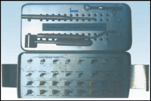
Fig. 4. ‘Innova’ implant kit
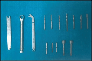
Fig. 5. ITI implant kit by Straumann
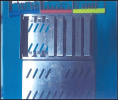
Fig. 6. Antrogyr implant kit
Insertion
Implants are provided in sterile pre-packed container with an implant carrier, which is gently taken to the drilled site and hand twisted to engage a few threads and then a special ratchet is used to screw the implant up to its required depth. The implant carrier is removed at this stage and the ‘healing cap’ or ‘cover screw is screwed on to the visible implant top.
Irrigation
It is one of the most important steps during the entire drilling process to keep the local bone temperature at surgical steps.
The surgical site is thoroughly cleansed and painted with 1% povidone iodine solution to bring down the bacterial colony count in the mouth.
It is worth while to note that mouth or oral cavity cannot be made sterile.
Incision
Standard trapezoidal incision or any other suitable incision as in case of Bränemark system buccal incision is made midway between the crest and depth of the vestibule and then flap is reflected lingually so that the implant, after insertion, is completely covered by mucoperiosteum to prevent leakage of oral fluid on to the implant site (fig. 7).
Drilling into Bone
The manufacturer gives a guide to the sequence of drills (sizes) to be used in order to make proper sized drill hole for a particular implant (fig. 8 and 9). Drilling is better than under, as it prevents crushing of bone ‘apical’ to implant.
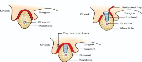
Fig. 7. Diagrammatic representation of flap reflection for Bränemark implants
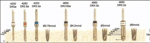
Fig. 8. Schematic representation of sequence in implant placement
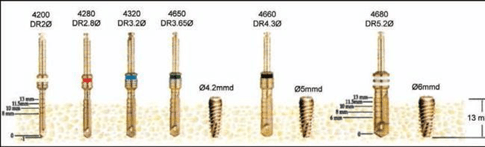
Fig. 9. Schematic representation of sequence in implant placemen
Drilling
The first drill invariably is the round one, to perforate the cortex at crest thereafter the drills are used in ascending order of thickness (diameter).
Drilling Speed
Bone must be drilled at a low speed. Generally a speed less than 800 rpm is recommended. The slower the better, as higher speed tends to raise the local temperature in bone and may be detrimental for the bone to remain viable and creep into the implant surface (roughened by plasma spraying or etching) to ultimately bring about osteointegration
The drills are marked for depth (fig. 8-9) to guide the surgeon as to how deep is the hole. Finally when the required depth is reached it is checked by the provided depth gauge. A little (1 mm or so) over normal body temperature and also to flush out the bone debris from the drill hole. Normal saline at room temperature is ideal for this purpose. ‘Very cold’ saline should be avoided as this might cause ‘Thermal shock’ in the local area in a restricted sense and it may be injurious to bone. Various types of ‘Physio dispensers’ are available commercially’ generally the manufacturer either provides one of their own or recommends a particular model (fig. 10 and 11).
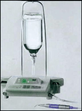
Fig. 10. Piezo ultrasonic physiodispenser unit mouth rinses
Closing the Wound
3’0 black silk is the preferred suture material with atraumatic curved needle. Interrupted sutures are placed and are removed 5-7 days postoperatively. Suitable antibiotics and non-steroid al analgesics are prescribed for 3-7 postoperative days. Chlorhexidine 0.2% w/ v mouth wash is added to the prescription at least 3-6 times daily for 7-20 days or even longer. This may be alternated with warm saline.
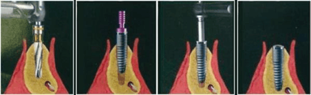
Fig. 11. Diagrammatic representation of sequence in implant placement
Complications
Intraoperative
- Tear of flap
- Lack of irrigation or in-sufficient irrigation
- Perforation of buccal or lingual cortex
- Implant / drill impinges on the inferior dental nerve
- Implant/ drill impinges on the neighbouring tooth root
- Perforation of maxillary sinus
- Perforation of pyriform fossa base
- Lack of primary stability of implants
- Rarely fracture of implant.
Immediate postoperative
- Pain (Unusual)
- Haemorrhage (rarely)
- Swelling
- Nerveinjuries.
Delayed
- Infection
- Secondary hemorrhage
- Nerve injury
- Loosening of implant
- Loss of implant.
Ailing v/s Failing Implant
Ailing implant is where there a radiolucent line like the period ontal ligament shadow in normal tooth (radiologically, best seen in intraoral periapical X-rays), this implant is likely to fail, but has a chance to survive if remedial measures are undertaken in time like local curettage to remove soft tissue from in between the implant and host bone (fig. 12).
A failing implant is one with the above along with 1° or 2° mobility. The chances of salvaging such an implant are bleak (fig. 12).
Healing Period
A period of 12-16 weeks is allowed of Osteointegration to take place. Only after this period has lapsed and the implant does not show any sign of ailing/ failing should the loading be undertaken.
Impressions for Loading
In single stage implant (where no second surgery is required to remove the healing caps), the healing cap is unscrewed and gingival former is screwed in and left for 7 to 17 days for gingival cuff to form around the future abutment.
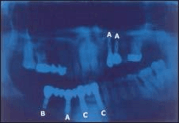
Fig. 12. (A) Ailing implant (B) Failing implant (C) Healthy (osteointegrated) implant
In two stages implants, second surgery is undertaken to remove the cover screw and put gingival former. After the requisite period, the provided impression posts (coping) are put onto the implant and impression is taken.
Then implant analogue is fixed on to the impression posts (coping) and the impression is poured in die stone. Once the plaster is set the post is removed and abutments are placed. The cast can then be sent to the laboratory for fabrication of prosthesis (crown). The abutment is taken off the cast leaving the implant analogue in the cast. This abutment can now be transferred and screwed onto the implant and prosthesis affixed to it (either cemented or screwed to the abutment).
Occlusal adjustment is undertaken if required (fig. 13 and 14).
Clinical Photographs
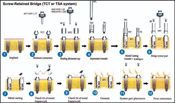
Fig. 13. Schematic representation of stages of screw retained prosthesis
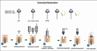
Fig. 14. Schematic representation of stages of cemented restorations
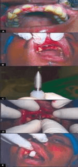
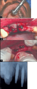
Fig. 15. (A) Preoperative intraoral view (B) Socket of freshly extracted teeth (C) Implant with carrier (D) Implant being hand tapped (E) Implant in the socket with its carrier (F) Implant being screwed in with ratchet (G) Implants in place and wound sutured (H) After suture removal (I) Intraoral periapical X-rays showing osteointegration
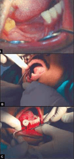
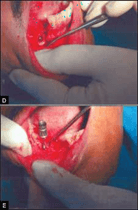
Fig. 16. (A) Preoperative intraoral view showing edentulous ridge (B) Drilled hole being tapped (C) Implant with implant carrier, being placed in the drilled hole (D) Implant placed (E)
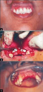
Fig. 17. (A) Preoperative intraoral view (B) Implants with cover screws in place (C) Healing of the wound
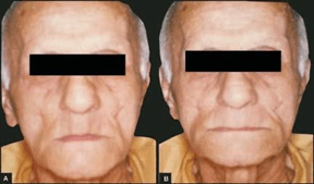
Fig. 18. (A) A 72-year-old male patient could not retain his lower denture, requested for implant supported denture. Preoperative frontal view, (B) Frontal view of the same patient, after the delivery of upper normal full denture and lower implant supported
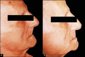
Fig. 19. (C) Predenture delivery profile, (D) Post denture delivery profile
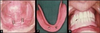
Fig. 20. (E) Two implants seen in mandibular canine region bilaterally, (F) Lower denture inner aspect – implant sockets in position
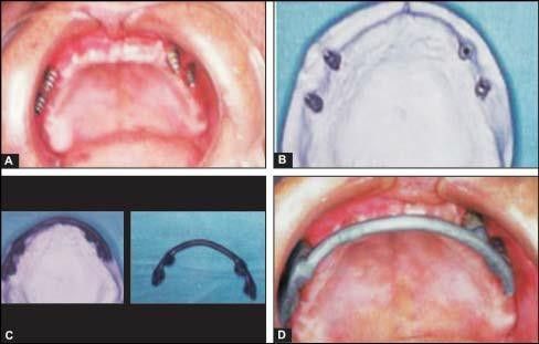
Fig. 21. (A) Four implants in place in maxillary edentulous ridge, (B) Plaster model with implant analogues(C) Castable dolder bar pattern prepared on the model, (D) Checking for the fit of the older bar in the mouth before the final finish
