
Introduction
With the rapid development of oil and gas drilling technologies, horizontal wells have become instrumental in enhancing hydrocarbon recovery and reservoir development efficiency. These wells provide increased reservoir contact, higher production rates, and improved recovery factors. However, horizontal drilling also introduces unique challenges, particularly in extended-reach sections, where torsional vibrations and stick-slip phenomena can significantly degrade drilling performance.
Top Drive Torque Management Systems (TDTMS) are unique technology which has the most promising results in managing the torsional vibrations and stick-slip phenomena. But, due to complexity of implementation, in many respects, become a double-edged sword in modern drilling. When fully optimized, these advanced real-time control solutions – initially developed to combat torsional stick-slip – can deliver remarkable drilling gains, such as enhanced rate of penetration (ROP), less wear on bottomhole assemblies (BHAs), and lower vibration-induced failures [5, 9]. In such best-case scenarios, TDTMS algorithms actively moderate torque and speed at surface, damping oscillatory energy before it propagates downhole. Operators often report significant reductions in nonproductive time (NPT) and notable cost savings, affirming TDTMS as a promising new-generation rig technology [3, 12].
Yet, alongside these success stories, TDTMS can quickly become a curse if poorly implemented or left unsupported by rig infrastructure and training programs. From 2013 to 2020, multiple field studies revealed that suboptimal parameter tuning – coupled with inadequate rig instrumentation and inconsistent crew engagement – could cause TDTMS logic to falter or worsen drilling vibrations. In those scenarios, even small parameter misalignments or torque-limit mismatches triggered continuous “over-limit” events, forced the system into inefficient control loops, and frequently led rig teams to dial back on drilling intensity. Instead of optimizing performance, TDTMS ended up yielding lower ROP, heightened fatigue on BHA components, and, at times, abrupt system shutdowns that added unplanned downtime. Moreover, the challenges of integrating TDTMS on older “legacy” rigs – where automation levels and sensor networks are uneven – further complicated attempts to harness the system’s full capabilities.
These unpredictable outcomes underscore how TDTMS’s effectiveness depends on a delicate interplay of rig power stability, formation characteristics, and real-time operator oversight [10]. Simply installing a TDTMS solution does not guarantee improvements; each rig site demands customized fine-tuning to account for unique friction profiles, downhole assemblies, and operating parameters. Through a series of anonymized global case studies, this paper investigates how TDTMS can yield extraordinary benefits when managed diligently – or degrade drilling results when critical elements of implementation and crew alignment are neglected. By consolidating lessons learned across diverse deployments, we strive to illuminate both the promise and the pitfalls of TDTMS – ultimately providing a roadmap for maximizing efficiency while avoiding the very real “curse” that arises from misapplication and poor synchronization with rig operations.
By examining real-world TDTMS deployments, this paper provides a roadmap for maximizing the benefits of this technology while avoiding the pitfalls of poor implementation. The integration of TDTMS into horizontal drilling operations demands a holistic approach, combining technological refinement with robust training programs, rigorous system testing, and dynamic parameter tuning.
Through lessons learned over the past decade, we demonstrate how TDTMS can transform horizontal drilling, delivering unprecedented efficiency gains and cost savings for operators worldwide. At the same time, we caution against the risks of underestimating the complexities of implementation. With the right strategy and execution, TDTMS can be a powerful enabler of modern drilling – but without proper oversight, it risks becoming the very challenge it was designed to solve.
Theoretical Summary
Stick-Slip Phenomenon
Stick-Slip arises when the rotational friction at the bit (or along the drillstring in highly deviated wells) exhibits a negative slope with respect to angular velocity. That is, once rotation slows or stops (the “stick”), static friction spikes above the dynamic friction level. When sufficient torque builds, the bit “slips” by suddenly accelerating to a speed often multiple times the nominal surface RPM. This high-speed phase then overshoots, eventually decreasing bit speed to near zero, repeating the stick-slip cycle [2; 8, p. 369-373].
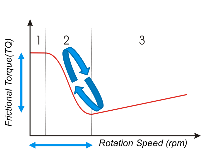
Fig. 1. Friction leading to torsional oscillations in Drill String
Stick-slip oscillation in drilling is a complex phenomenon that stems from the interaction of forces within the drill string and bit as they engage with the formation. This dynamic behavior can be understood as the cyclic alternation between two phases: the "stick" phase and the "slip" phase.
Stick Phase:
During the stick phase, the bit momentarily halts its rotation due to excessive resistance or friction at the bottom of the hole. While the bit remains stationary, torsional energy builds up along the length of the drill string as the surface top drive continues to rotate. The drill pipe essentially behaves like a twisted spring, storing elastic potential energy.
Slip Phase:
Eventually, the accumulated energy exceeds the frictional resistance at the bit-rock interface, causing the bit to suddenly release and spin at a much higher rotational speed than intended. This abrupt release is the "slip" phase, during which the stored torsional energy propagates along the drill string as a wave.
Consequences of Stick-Slip:
- Torque Fluctuations: The drill string experiences large cyclic variations in torque, with sharp spikes that can exceed the equipment’s design limits.
- Bit Damage: During the slip phase, the bit can rotate at extremely high speeds, leading to accelerated wear and even catastrophic failure.
- Efficiency Losses: The alternation between sticking and slipping disrupts the steady progress of drilling, reducing the rate of penetration (ROP).
- Structural Stress: The cyclic nature of stick-slip induces fatigue in the drill string, increasing the risk of twists or breaks.
Torsional Wave Propagation and Reflection Coefficients
From a vibrational standpoint, the drillstring can be approximated as a transmission line for torsional waves [6, 9]. A change in bit friction or downhole torque generates a torsional wave that travels up the pipe at a speed typically near 3100 m/s for steel. Key parameters include:
- Torsional Wave Speed,
 , where G is the shear modulus and ρ is the steel density.
 - Characteristic Impedance,
 , with being the pipe’s polar moment of inertia (corrected for tool joints).
 - Reflection Coefficient, r defined by the ratio of reflected to incident wave.
When a torsional wave encounters the top drive, part of the wave energy may be reflected downhole if the top-drive impedance (or equivalently, the inverse of mobility) is high. Conversely, a “smart” or “soft” drive effectively absorbs more of the wave energy by lowering its impedance at the stick-slip frequency range–thus damping the torsional oscillations [5, 10].
Drive Impedance and Mobility
A common way to model top drive behavior is by treating the drive and its controller as an impedance (or its inverse, mobility) acting on the drillstring:
![]() , (1)
, (1)
Where ![]() is the oscillatory torque at the drive output shaft, and
is the oscillatory torque at the drive output shaft, and ![]() is the corresponding fluctuation in angular speed. When a specialized speed controller or torque-feedback loop is added, the effective drive impedance becomes frequency-dependent. In broad terms:
is the corresponding fluctuation in angular speed. When a specialized speed controller or torque-feedback loop is added, the effective drive impedance becomes frequency-dependent. In broad terms:
- High drive impedance → Strong wave reflection at surface → Poor damping of stick-slip.
- Moderate/Low drive impedance → Better wave absorption → Enhanced damping.
To tailor the drive impedance (or mobility) specifically at the fundamental stick-slip frequency, modern systems employ advanced PID or PI controllers with real-time torque feedback, digital filters, or “inertia compensation” terms to widen the absorption bandwidth [3, 9].
Control Strategies to Mitigate Stick-Slip
Numerous control algorithms have been proposed and implemented:
- Torque-Feedback Systems. These systems directly measure string torque via a sensor or infer it from drive parameters, then rapidly adjust top-drive RPM to counteract the torsional waves [5].
- Soft Torque and Cascade Feedback. Developed originally by Shell [12, 13], Soft Torque uses a combination of stiff speed control in the inner loop and a mobility-tuned outer loop to absorb oscillatory energy. A high-pass or band-pass filter differentiates between low-frequency load variations and higher-frequency stick-slip modes [3].
- SoftSpeed. Instead of adding a separate cascade loop, SoftSpeed [9] modifies the speed controller’s proportional and integral (PI) gains so that the top-drive impedance drops specifically around the measured or predicted stick-slip frequency. Optional acceleration-feedback (“inertia compensation”) term further broadens the bandwidth if time delays are minimized [10].
- Z-Torque. A more recent approach that likewise relies on feed-forward or feed-back of measured torque but aims for near-full impedance matching across a wide frequency band. Its effectiveness, however, can be highly sensitive to signal delays and the precision of measured or inferred torque [3].
In all these approaches, time delays (e.g., from sensor filtering, PLC scan times, or data transmission) and system limits can degrade performance or even destabilize higher modes. Maintaining robust, low-latency without external interference feedback is therefore essential [10, 11].
Importance of Accurate Modeling and Tuning
Traditionally, the success of any top drive torque management system (TDTMS) was believed to hinge on four critical parameters:
- Accurate lumped or distributed models of the drillstring, including BHA inertia and multi-section pipe.
- Realistic friction models capturing negative damping regions.
- Low time-lag instrumentation to ensure real-time response to oscillations.
- Proper auto-tuning or operator tuning procedures to match the actual stick-slip frequency.
While accurate modeling and tuning remain foundational to the performance of Top Drive Torque Management Systems (TDTMS), field implementations across diverse environments and rig setups reveal a surprising trend: these four traditionally critical parameters–accurate modeling, realistic friction analysis, low-lag instrumentation, and precise tuning–are rarely the primary culprits behind performance issues. In fact, extensive operational data shows that in 95% of cases, these elements are well-designed and functional.
Instead, the challenges impacting TDTMS effectiveness are predominantly rooted in rig system limitations and the interfaces between the TDTMS and the broader operational systems on the rig.
While modern TDTMS technologies such as SoftSpeed™, Soft Torque, and Z-Torque™ incorporate advanced features like automated frequency detection to reduce reliance on manual tuning [9, 10], field data underscores that even the most sophisticated systems can underperform when rig-level challenges remain unaddressed.
Comparing System Architectures: ElectroProject vs. NOV Approaches. TDTMS technologies can generally be categorized into two system families: those following the ElectroProject logic (e.g., SoftTorque, Z-Torque) and those developed by NOV (e.g., SoftSpeed I & II generations).
- ElectroProject Systems: These systems use drillstring input to calculate vibration parameters (e.g., Kn and Fn), applying the tuning directly to the top drive. This approach allows for faster stabilization, particularly at shallower depths (up to 12,000 ft), and enables performance even when drilling off-bottom.
- NOV Systems: These rely on raw drilling torque as the primary input to define stick-slip parameters. The drillstring is used to calculate bit RPM, with torque interpreted as a function of multiple inputs.
While accurate modeling and tuning remain critical to TDTMS success, field data highlights the equal importance of addressing rig system integration issues. Power stability, sensor latency, and real-time system feedback must be prioritized to fully leverage advanced torque management technologies.
By addressing these rig-level integration challenges, TDTMS deployments can deliver their full potential, unlocking significant improvements in drilling efficiency, safety, and cost-effectiveness.
Transition: Rationale and Field Implementation Gaps
Despite substantial advancements in Top Drive Torque Management Systems (TDTMS) over the past decade, significant gaps persist in their field implementation. From the first deployments in the Middle East in 1990s to global adoption by 2020, many lessons have highlighted the critical importance of rig-specific integration, system feedback compatibility, and real-time control protocols. While laboratory and pilot tests consistently demonstrate TDTMS’s potential to reduce stick-slip, enhance steering efficiency, and safeguard drilling assemblies, real-world deployments often face unanticipated operational challenges.
A key realization from field data is that the majority of implementation failures are not due to inadequacies in TDTMS design–such as modeling, tuning, or frequency detection–but rather due to rig system limitations and poor integration of the torque management system with the rig’s broader operational infrastructure. Challenges such as inconsistent power distribution, incompatibility with AutoDriller systems, Top Drive limitations, heave compensation interference, and sensor latencies often prevent the TDTMS from functioning as intended. These rig-specific constraints can lead to degraded performance or, in some cases, exacerbate torsional vibrations, causing more harm than benefit to drilling operations.
Furthermore, personnel training and interpretation of TDTMS outputs are frequently overlooked aspects of implementation. Crews unfamiliar with TDTMS behavior often misinterpret its performance metrics or fail to address system warnings, inadvertently diminishing its effectiveness.
To underscore these implementation realities, the following sections will present anonymized case studies from international TDTMS deployments.
By consolidating these lessons learned from diverse international experiences, our goal is to provide actionable insights and create a roadmap for future TDTMS deployments. This roadmap will emphasize:
- Addressing rig-specific integration challenges.
- Enhancing personnel training to interpret and act on system feedback.
- Optimizing implementation workflows to ensure alignment between TDTMS and rig infrastructure.
To illustrate these implementation realities, the following sections will show anonymized examples of TDTM deployments in various wells and regions–omitting or masking any site-specific identifiers and customer references. Our aim is to demonstrate how, even with sophisticated software (e.g., SoftSpeed™) and hardware upgrades, field execution is the final determinant of success.
By consolidating these diverse international experiences, we hope to foster a roadmap for future TDTM deployments that maximizes return on investment, minimizes nonproductive time (NPT), and facilitates safer, more efficient drilling.
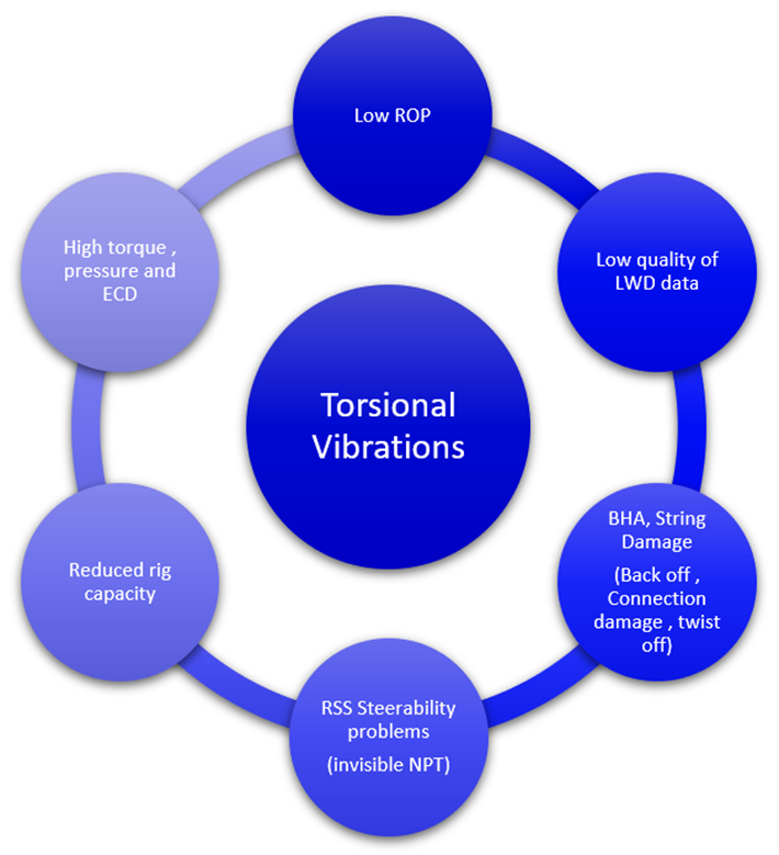
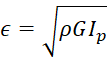
Fig. 2. Illustrating the Effect of Torsional Vibrations on Drilling Performance
Figures 2 highlight the profound negative impact that excessive torsional vibrations, including the stick-slip phenomenon, can have on drilling performance. Large variations in downhole torque and abrupt changes in bit speed lead to reduced Rate of Penetration (ROP), driven primarily by torque limitations. Field observations consistently link these performance dips to uncontrolled torque fluctuations and cyclical stick-slip behavior, where torque swings reach up to 50% above planned levels. This often triggers premature torque limit activation, resulting in a significant reduction in the available power to drill rock effectively.
Beyond the immediate effect of torsional vibrations on ROP, there exists a wide array of hidden side effects that indirectly but critically reduce drilling efficiency. These effects include:
- Pressure and ECD Fluctuations: Torsional vibrations induce axial load changes along the drillstring, which, combined with dynamic effects, result in variations in standpipe and annular pressures. In deep, ultra-extended reach (ERD) bores, field data has recorded up to 400 psi standpipe pressure swings and 0.5 ppg variations in Equivalent Circulating Density (ECD). While the exact physics of this phenomenon are still under study, the field-validated effect demonstrates that drilling with severe stick-slip vibrations at 400 RPM creates significantly greater pressure instability compared to a stationary string or stable 120 RPM operation.
- Reduced Rig Torque Capacity: Often overlooked, the available rig Torque-RPM capability is heavily discounted in the presence of torsional vibrations. As a result, the effective depth a rig can drill is drastically reduced. Surface torque variations can swing up to 50%, prematurely activating torque limits. For example, in the same field and using identical BHAs, rigs equipped with fully calibrated Top Drive Torque Management Systems (TDTMS) extended torque capacities to depths beyond 30,000 ft, whereas rigs without TDTMS maxed out at 20,000–22,000 ft.
- Compromised LWD Data Quality: Severe torsional vibrations often degrade Logging While Drilling (LWD) data quality. Downhole RPM swings exceeding 600 RPM disrupt azimuthal data alignment, causing tools to misinterpret quadrants and deliver averaged values. This jeopardizes geosteering operations, particularly in ERD wells, where precise directional data is critical.
- Reduced Steering Efficiency and ROP: Extreme RPM fluctuations destabilize the tool face of Rotary Steerable Systems (RSS), leading to poor directional control. Directional drillers frequently adjust drilling parameters to mitigate these effects, resulting in hidden performance reductions. These inefficiencies increase overall well construction time and add to operational costs.
- Increased Wear and Damage to Downhole and Surface Equipment: Repeated high-frequency vibrations accelerate fatigue in drillstring components, risking premature tool failure. Surface equipment, including top drive systems, also experiences elevated wear and tear, requiring more frequent maintenance and replacement of critical components.
A well-implemented TDTMS actively absorbs or modulates torsional energy, disrupting the stick-slip cycle and ensuring a smoother torque and RPM profile. Advanced control algorithms stabilize bottomhole parameters, allowing for higher, more consistent ROP. By analyzing real-time data and dynamically tailoring top drive responses, these systems protect the Bottom Hole Assembly (BHA), reduce rig stress, and enhance steering efficiency–all of which contribute to minimizing well construction time.
However, the success of TDTMS hinges on proper system integration with rig systems, accurate and timely sensor feedback, and crew readiness to interpret and act on system outputs. Field data consistently shows stark performance contrasts between operations with “TDTMS on” and “TDTMS off.” When leveraged effectively, TDTMS bridges the gap between potential and actual performance, delivering technical and financial benefits while safeguarding equipment and ensuring operational consistency.
Field Observations and Lessons
Since the late 1980s, Top Drive Torque Management Systems (TDTMS) have been introduced worldwide to address torsional vibrations in drilling operations. Despite their potential, these systems initially gained little traction in the execution phase, largely due to a lack of awareness and skepticism from rig teams. The term “string stall” became a prevalent concern, as the system's mechanisms were often misunderstood or perceived as counterproductive to operational efficiency.
Our field implementation of TDTMS began in 2013 in the Arabian Gulf, targeting extreme torsional vibrations in ultra-extended reach drilling (ERD) horizontal wells. At the onset, the reception from rig crews was overwhelmingly negative. Comments like “The top drive is stalling!”, “It will burn the top drive!”, and “The system says ‘No S&S,’ leave it alone!” highlighted the deep-seated resistance to the technology. This resistance stemmed from a lack of training and understanding among drillers and rig teams, who were unfamiliar with how TDTMS operates and its benefits.
A recurring challenge was the perception of reduced top drive RPM during TDTMS operation. Crew members instinctively believed that any drop in RPM signaled a malfunction or impending failure of the top drive. As a result, they often deactivated the system or picked the bit off-bottom prematurely, undermining the system’s ability to mitigate torsional vibrations. This misinterpretation led to a cycle of inefficiency and skepticism about the system’s value.
A critical turning point in the implementation process was addressing this knowledge gap through targeted training programs. Initially, we focused on educating drillers about the theory and practical aspects of TDTMS. Over time, this training expanded to include the entire rig crew and operator teams, ensuring a comprehensive understanding of the system's functionality. Key elements of the training included:
- Recognizing System States: Teaching crews to distinguish between "On," "Off," and "Calibration-Unstable" states of the TDTMS.
- Understanding TDTMS Dynamics: Explaining how the system actively manages torque fluctuations, reduces stick-slip, and enhances overall drilling performance.
- Practical Applications: Demonstrating real-world scenarios where TDTMS mitigated torsional vibrations, improved Rate of Penetration (ROP), and protected downhole tools from damage.
The initial steps of implementing Top Drive Torque Management Systems (TDTMS) in the field were aimed at educating the rig team on recognizing the system’s operational states – "On," "Off," and "Calibration-Unstable" – using the drilling parameters they were actively monitoring. The provided figure 3. illustrates the progression from “No Solution,” through an “Unstable Solution,” to achieving a “Good Result”.
- No Solution: In the first state, the system is not active, leading to pronounced stick-slip oscillations, as seen in the significant fluctuations in torque (blue curve) and rotational speed. This results in inefficient drilling, increased tool wear, and system instability.
- Unstable Solution: The second state reflects an improperly calibrated system, where partial mitigation of stick-slip is achieved but inconsistencies in torque and RPM persist. This phase highlights the importance of tuning the system to account for the unique wellbore and drilling environment parameters.
- Good Result: The final state demonstrates the system in optimal operation, where torque fluctuations are minimized, stick-slip is effectively mitigated, and the overall stability of the drilling process is restored. This results in higher efficiency, reduced wear on equipment, and improved drilling performance.
By teaching crews to identify these states visually and interpret the associated data trends, the implementation process transitioned from skepticism to informed use. This step-by-step approach fostered greater trust in the system and laid the groundwork for long-term adoption of TDTMS in complex drilling operations.
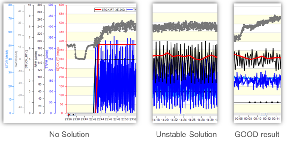
Fig. 3. TDTMS system signature of the Drilling mechanics logs for each state
Zone Differentiation: Performance and Efficiency
As part of the more advanced training, detailed analysis of system performance was introduced through zone differentiation. Figure 4 and the accompanying charts illustrate three distinct operational zones of TDTMS efficiency, serving as a guide for system performance monitoring and troubleshooting. ese systems can transition into unstable modes of operation due to several limiting factors. These include insufficient power supply, reaching top drive capacity limits, torque restrictions influenced by Bottom Hole Assembly (BHA) design, and elevated friction factors (FF). Understanding these transitions and their impact on drilling efficiency is crucial for optimizing system performance.
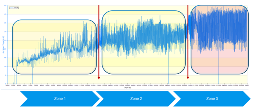
Fig. 4. TDTMS Performance Zoning
The figure 4. illustrates the performance of TDTMS across different operational zones. It serves as a benchmark for evaluating the effectiveness of any TDTMS implementation. By analyzing data from wells with over 20,000 feet of open hole in an 8.5-inch carbonate reservoir section, the study provides a practical framework for assessing system efficiency across distinct operational conditions.
The creation of these zones allows differentiation of TDTMS efficiency and highlights areas for potential improvement. Importantly, while the system's torsional vibrations/Stick & Slip limits remain constant, the zones provide a detailed perspective on how TDTMS mitigates torque fluctuations and enhances drilling performance under varying conditions.
This advanced zone analysis underscores the importance of managing drilling parameters and torque feed-forward (FF) to navigate between zones effectively. By identifying and addressing the factors contributing to unstable modes, operators can maximize the benefits of TDTMS and ensure consistent performance even in challenging drilling environments.
Zones descriptions and features:
1. Zone 1: High-Efficiency Operation (80–100%):
- Torque oscillations: 10–15%.
- Surface RPM variations: 10–15%.
- Surface and downhole RPM: Stable and matching.
- Stick and Slip Indicator (S&S): <90%.
- Impact: Smooth drilling with high stability and effective vibration mitigation.
2. Zone 2: Moderate Efficiency (50%):
- Torque oscillations: 20–60%.
- Surface RPM variations: 30–70%.
- Surface and downhole RPM: Mismatched with erratic behavior.
- S&S: >100%.
- Impact: Noticeable instability in torque and RPM, but with some vibration reduction. Turning off TDTMS at this stage would exacerbate downhole vibrations.
3. Zone 3: Low Efficiency (10%):
- Torque oscillations: 60–80%.
- Surface RPM variations: 50–80%.
- Surface and downhole RPM: Significant mismatch with multiple stops.
- S&S: >300%.
- Impact: Severe RPM fluctuations leading to automatic deactivation of TDTMS below 16 RPM. Manual reactivation is required.
Transitioning Between Zones
The training emphasized strategies to transition between zones, particularly from Zone 2 to Zone 1. This involves:
- Optimizing drilling parameters, such as weight-on-bit and surface RPM.
- Managing torque friction factors (FF) to minimize oscillations.
- Calibrating the system to align with specific wellbore conditions.
Recommendations for Successful TDTMS Implementation
The cornerstone of further training for field teams was the establishment of an effective and meticulous preparation framework designed to align the system, rig configuration, and crew readiness. This approach ensures that Top Drive Torque Management Systems (TDTMS) operate optimally under the expected well conditions while minimizing potential inefficiencies or malfunctions. By instilling a structured methodology, we aimed to empower field teams with the knowledge and tools necessary to maximize system performance and enhance drilling efficiency across various environments:
- Depth Interval vs. TDTMS Configuration Standard Systems (SoftSpeed, Torque Feedback): Suitable for wells in the 1000–4500 m range, where torque demands remain within manageable limits. Advanced Systems (SoftSpeed II, Z-Torque): Recommended for deeper wells exceeding 4500 m or in challenging formations with high torque fluctuations. These systems perform better under extreme conditions due to enhanced frequency response and wider torque absorption bandwidth.
- BHA Alignment Confirm that the TDTMS software's bottomhole assembly (BHA) directional assumptions align with on-site tool configurations. Ensure accurate top-to-bottom references in the BHA setup to avoid misalignment, which can lead to unstable TDTMS performance.
- Training and Logging Provide drillers with detailed "quick guides" covering the following, how to handle short versus long stick-slip period settings & Step-by-step instructions for auto re-engagement after TDTMS is switched off. Emphasize the visual indicators of system states (On/Off/Calibration-Unstable) and their associated torque and RPM behaviors.
- Calibration and Baseline Testing Conduct baseline torque and RPM tests to establish pre-job performance benchmarks. Verify that rig sensors provide accurate, real-time data for monitoring torque and RPM stability.
- Power and Rig System Validation Assess the rig's power distribution system to ensure stable generator loads, particularly during high-torque operations. Confirm synchronization between TDTMS and AutoDriller systems to avoid aggressive weight-on-bit (WOB) ramp rates that can destabilize torque.
Drilling Execution phase
Once drilling commences, maintaining torque and RPM stability becomes critical. The following strategies help operators manage TDTMS performance in real time and transition between zones effectively:
- Monitoring Torque and RPM Stability – Continuously monitor torque and RPM fluctuations to identify instability: If fluctuations exceed 50% of mean values (as indicated in Figure 2: “amplitude > 50%”), initiate corrective measures: Method 1: Temporarily switch off TDTMS for 3–5 minutes, apply lower drilling parameters, and then re-engage the system. Method 2: Pick up off-bottom, stop RPM, release torque, re-apply WOB, and engage TDTMS at moderate RPM. Observe whether stability improves within a few minutes of corrective action.
- Auto-Driller Synchronization – Confirm that WOB ramp rates are optimized for each depth interval to prevent excessive load spikes that exceed the TDTMS’s compensation capabilities.
- Transitioning Between Zones – Use real-time zone identification (Zone 1: High Efficiency, Zone 2: Moderate Efficiency, Zone 3: Low Efficiency) to guide parameter adjustments: For Zone 3, where efficiency is minimal, reduce RPM and torque setpoints incrementally to stabilize the system. Transition to Zone 1 by optimizing torque feedback settings and reducing friction factors (FF) through lubricant adjustments or BHA changes.
Post-Job Analysis and Continuous Improvement
The post-job phase is crucial for refining TDTMS configurations and ensuring long-term system performance. Analyzing field data and incorporating crew feedback provides actionable insights for future deployments:
- Record the “Over-Limit” Events – Record all instances of TDTMS torque-limit activations or drastic RPM drops. Identify patterns and correlate these events with specific drilling parameters or depth intervals.
- Correlate Generator Configurations – Document changes in generator loads or configurations (e.g., shifts from 3 to 4 generators) and assess their impact on TDTMS stability.
- Crew Feedback and Training Updates – Conduct post-job interviews with drillers to gather feedback on system usability and perceived challenges. Address any confusion about stick-slip period settings, re-engagement procedures, or troubleshooting techniques.
- Performance Review and Optimization – Use post-job data to refine future pre-job setups, improving calibration and operator preparedness.
By integrating pre-job checks, real-time operational strategies, and post-job reviews, operators can fully harness the potential of TDTMS technology. This structured approach not only enhances drilling performance but also ensures a seamless alignment between the system, rig configuration, and crew expertise. As demonstrated through zone-based analysis, successful TDTMS deployment requires more than advanced algorithms; it demands a commitment to continuous learning, proactive system tuning, and collaboration between operators, rig contractors, and service providers. This proactive methodology transforms TDTMS from a theoretical solution into a practical tool for driving efficiency and innovation in modern drilling operations.
Conclusion
The advancement of Top Drive Torque Management Systems (TDTMS) has been transformative for modern drilling operations, addressing persistent challenges such as torsional vibrations, enhancing Rate of Penetration (ROP), reducing vibration-induced failures, and safeguarding critical downhole components. However, the field data and case studies presented in this paper emphasize that TDTMS success depends not only on its technological capabilities but also on its effective integration with rig systems, operational workflows, and operator expertise.
TDTMS is not a simple plug-and-play solution. Poor calibration, inconsistent power distribution, mismatches with AutoDriller systems, and insufficient operator training often lead to underwhelming results, negating the potential benefits these systems are designed to provide. Detailed performance zone analyses further reveal that TDTMS efficiency can decline sharply when system parameters are not aligned with rig-specific dynamics and operational needs. This highlights the critical importance of addressing both technical and human factors during implementation.
By proactively closing these gaps-through precise system tuning, robust crew engagement, and investment in operator training-TDTMS can realize its full potential, revolutionizing the efficiency and safety of horizontal and extended-reach drilling operations. Importantly, this paper demonstrates that even modest investments in training and system integration can yield significant returns, proving that the true value of TDTMS lies in its ability to align advanced algorithms with real-world operational constraints.
For the Russian oil and gas industry, particularly in the context of offshore exploration and long horizontal drilling in challenging reservoirs, TDTMS represents a vital opportunity. With a growing focus on offshore fields in the Arctic shelf, the Caspian Sea, and other complex environments, efficient and reliable drilling technologies are essential. TDTMS offers a path to mitigate the unique challenges of these operations, including harsh environments, deepwater conditions, and extended-reach wells.
In conclusion, TDTMS stands as a pivotal tool for the future of drilling, delivering unparalleled benefits when implemented effectively. By recognizing and addressing the barriers discussed in this paper, operators can overcome the “curse” of inconsistent performance and fully unlock the technology’s potential to deliver sustainable, measurable improvements in well delivery.
For Russia’s oil and gas sector, TDTMS offers a roadmap to revolutionize offshore and horizontal drilling operations. By leveraging tailored implementation strategies, addressing power and system integration challenges, and prioritizing proper training, operators can achieve substantial performance gains, reduce costs, and enhance safety. The case studies in this paper underscore that through effective deployment, TDTMS can drive innovation, efficiency, and reliability, positioning the Russian market as a leader in advanced drilling operations.
Acknowledgments
The author thanks all rig crews, drilling engineers, and field specialists who supported data gathering from 2013 to 2020 across multiple regions. Their operational insights and detailed feedback were instrumental in forming the lessons and recommendations outlined in this paper.
