I. Introduction
Currently, microstrip antennas (MPA) are widely used in the field of telecommunication systems due to various advantages: thin profile, low weight, conformity, the possibility of having circular polarization waves, the possibility of implementing multi-frequency antennas, integration with the power supply circuit in antenna arrays, low cost and simple implementation. However, despite a number of advantages, its main disadvantage is its narrow band.
while the need for broadband antennas has become increasing, we aim in this paper to design a broadband microstrip antenna. Due to the presence of many antennas that are suitable for use on a wide band, we will mention the elliptical antenna because of its ease of design and manufacture. While the conventional elliptical antenna is not optimal for use as a Gaussian pulse filter we will use elliptical slots in the dipole arms, and their effect on antenna performance will be demonstrated during antenna design [6].
The next step is to choose the appropriate antenna feeding method, this process represents the connection of the antenna with other devices in the communication system (transmitter or receiver). The most used method in integrated circuits and millimeter waves is by using microstrip lines. When using microstrip lines to feed the dipole, we need to use MS-to-CPS to ensure proper feeding to both ends of the dipole.
There are many MS-to-CPS transactions (baluns) which secure the wide bandwidth, we will use the model developed in [2] which secures 180° phase difference between the two balun branches in addition it should achieve a fairly low and equal reflection coefficient between the two balun branches.
The traditional elliptical antenna, as it is known, has one degree of freedom, which is one radius, which limits the possibility of controlling the antenna parameters. The antenna used in this work has an additional feature which is the presence of a slot, which adds an additional degree of freedom to control the antenna parameters. The elliptical slots increase the gain of the antenna in the upper portion of the band. The width of the inner (cutout) ellipse affects the return loss, while the length of the inner ellipse generally affects the gain performance.
II. Antenna Design
The proposed antenna is designed using CST Microwave Studio (www.cst.com). The outer elliptical patch has axes length of R1 (major axis) and R2 (minor axis) equal to 3 mm and 2.23 mm respectively. The inner elliptical patch has axes lengths of R3 (major axis) and R4 (minor axis), equal to 8 mm and 6 mm respectively. The proposed antenna is designed on FR4 substrate having dimensions 20mm × 24mm with thickness H=1mm and dielectric primitivity of 2.4.
The feed arrangement is applied to excite antenna geometry using MS-CPS transaction through following steps [2]:
- Design the 50-ohm microstrip CPS line at the terminal of the transition.
- Design the 100-ohm CPS line at the terminal of the balun.
- Design the two strip lines that gives 180-degree phase difference. The two lines have the same bends, but their length differ by a half of a wavelength.
- Design a quarter wavelength transformer that has a 35-ohm line impedance.
The proposed design is shown in fig.1.
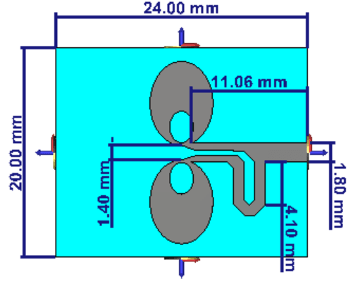
Fig. 1. Top view of the proposal antenna
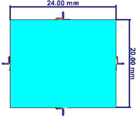
Fig. 2. Back view of the proposal antenna
III. Results and discussion
The simulated variation in reflection coefficient as a function of frequency for the proposed antenna is shown in fig 2. It is apparent from fig 2 that the proposed antenna covers the frequency band from 11 GHz to 15 GHz. The VSWR (Voltage Standing Wave Ratio) is well below 1.5 at the frequency band [11-15 GHz] as shown in fig 3.
The gain of the antenna is between 3dB (at the minimum frequency) and 4 dB (at the maximum frequency), In the entire range of frequency, variation in gain is less than 1dB.
Design guidelines [8]:
- By decreasing the dimensions of the outer ellipse, the lower operating frequency increases.
- The elliptical slots increase the gain of the antenna in the upper portion of the band.
- The overall dimensions of the dielectric affect both the gain and return loss of the antenna.
- The width of the inner (cutout) ellipse affects the return loss.
- The length of the inner ellipse generally affects the gain performance.
- The inner ellipse offset value plays an important role in achieving a high-gain performance over the operating band.

Fig. 4. Theoretical VSWR of the proposed antenna
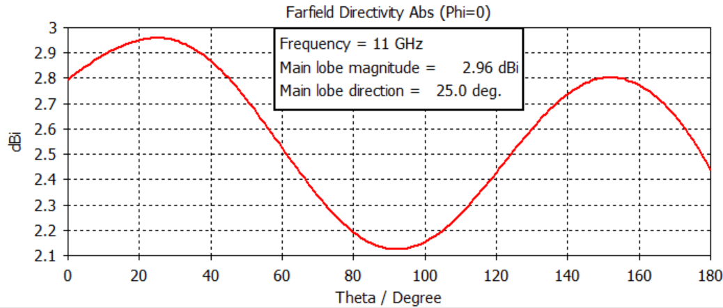
Fig. 5. Theoretical radiation patterns at 11GHz
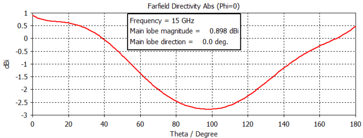
Fig. 6. Theoretical radiation patterns at 15GHz
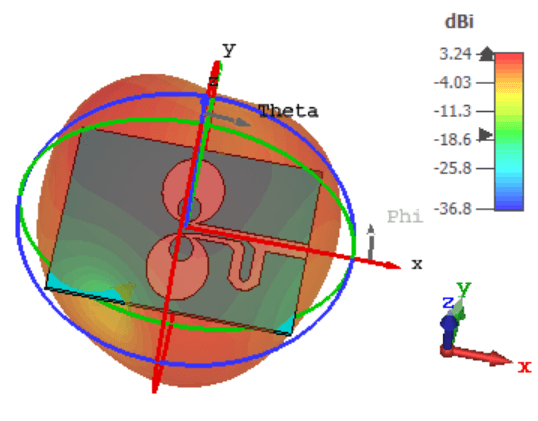
Fig. 7. Theoretical 3D radiation pattern at 13 GHz
Conclusion
In this paper, a new design of elliptical dipole with inner elliptical slots (cutouts) using a MS-CPS (Microstrip to Coplanar strips) is proposed for Ku band applications. The antenna operates efficiently at the frequency band [11-15 GHz] with VSWR less than 1.5. the proposed antenna can be used for all kind of telecommunication systems where an ultra-wide band is required.

.png&w=640&q=75)