.png&w=384&q=75)
Introduction
Wind power has been used for about 3,000 years. Until the early twentieth century, wind power was used to provide mechanical power for pumping water or grinding grain. At the beginning of modern industrialization, the use of fluctuating wind power was replaced by fossil fuel engines or the electrical grid, which provided a more stable source of power. In the early 1970s, with the first oil price shock, interest in wind power resurfaced. However, this time the focus was on wind power rather than mechanical power. Due to the problems facing the environment, the clear increase in carbon dioxide, economic instability and the increase in population density, it is necessary to rethink the search for alternatives to energy sources, especially non-traditional energies, including renewable energy sources such as solar and wind energy, especially for remote and isolated areas that are difficult to reach or deliver fuel and energy to these areas, as these alternatives can be used for domestic uses, which contributes to improving environmental conditions [1, p. 1-6; 2]. One of the most modern renewable energies in use is wind energy, as wind energy is an irregular and unstable source and is characterized by its momentary fluctuations [2, 3].
Non-renewable energy consumption is responsible for their total depletion, so the development of alternative energy is inevitable. The demand for electricity and the desire to minimize environmental damage have led to a greater reliance on renewable sources of electricity. Wind generators are of greatest importance among them. Electricity generation systems based on the use of wind energy use the conversion of wind kinetic energy into mechanical energy of the generator rotation. Using the mathematical description of an idealized wind turbine, it is possible to estimate the value of the speed at which the turbine power and system efficiency are maximum.
One of the key electrical challenges in wind energy generation is the inherently random and variable nature of wind. To address this in wind-to-electricity conversion systems, Maximum Power Point Tracking (MPPT) strategies are implemented to optimize efficiency [1, p. 1-6]. The output power of a wind turbine varies with wind speed, and due to the unpredictable characteristics of wind, achieving maximum power output across all wind conditions is complex.
This study explores a control approach for a 20-kW small-scale horizontal-axis wind turbine that aims to maximize power output under fluctuating wind speeds. The main operational characteristics of the turbine are analyzed, and a mathematical model of a high-speed control system tailored for MPPT implementation is developed.
The following assumptions are made: air compression is neglected during turbine rotation, and power losses in components like the gearbox and inverter are disregarded. Only aerodynamic losses – specifically, the portion of wind energy not converted into torque and passing through the turbine – are considered.
Reference [4, p. 10-15] introduces an original method for modeling small-scale wind turbines based on their technical parameters. The paper proposes an enhanced mathematical model that incorporates both the power coefficient (CpC_pCp) and torque coefficient (CtC_tCt). Additionally, control is achieved by adjusting the blade pitch angle (β\betaβ), allowing optimization of the output speed for maximum power extraction.
1. Wind turbine operation mode
Modern wind turbines can function in two operational modes: constant rotor speed and variable rotor speed. The turbine’s performance is typically categorized into four distinct regions, as depicted in figure 1. Of these, only the second and third regions represent active operation, while the first and fourth are considered inactive.
Region 1 corresponds to wind speeds below the cut-in threshold (typically less than 5 m/s), during which the turbine remains stationary and does not generate power.
Region 2 spans from the cut-in wind speed to the rated wind speed i.e., when wind speed exceeds 5 m/s but remains below the nominal speed vnomv. In this range, the turbine actively produces power. Two primary control strategies are applied in this region to optimize performance: adjusting the blade pitch angle (i.e., angle of attack in the horizontal plane) and modifying the generator’s rotational speed.
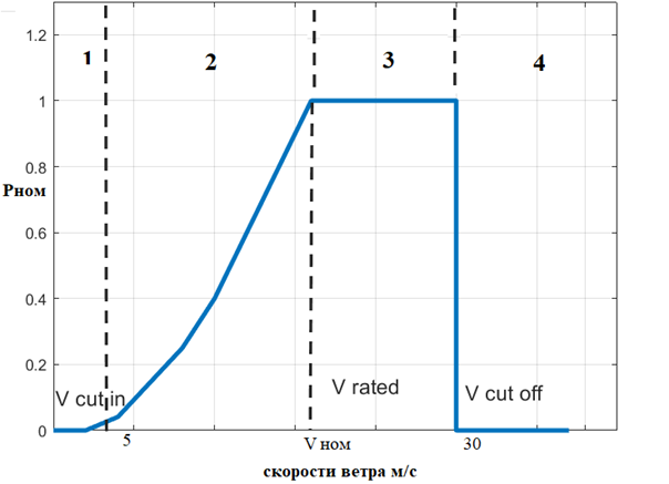
Fig. 1. Of the wind turbine operation mode [5]
Region 3 lies between the cut-in and cut-out wind speeds, typically when wind speeds exceed nominal levels but are below the maximum safe limit (above 5 m/s and up to around 30 m/s). This is the range in which the turbine generates the maximum amount of energy. However, to prevent overloading the generator's electrical and mechanical systems, the turbine cannot harness all available wind energy. In this region, the turbine operates at a constant rotational speed and maintains a rated power output. To regulate excess energy and ensure safe operation, the blade pitch angle is actively adjusted.
Region 4 represents conditions where the wind speed exceeds the cut-out threshold (typically above 30 m/s). At this point, the turbine is shut down to prevent mechanical damage from excessively high winds. To protect the system, the blades are rotated to a pitch angle of 90°, effectively stopping the rotor and preventing further energy capture [5].
Mathematical description of wind turbine aerodynamics
A Wind Energy Conversion System (WECS) converts kinetic energy from the wind into mechanical energy and subsequently into electrical energy. The modeling involves aerodynamic, mechanical, and electrical subsystems. Below is a breakdown of each major component of the mathematical model.
When describing the model, equations (1-5) were used in [5; 6, p. 1-9; 7; 8, p. 163-168; 9, p. 917-921].
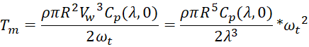
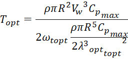
The turbine's torque is dependent on the wind speed. v w, which acts on its blades, the power utilization factor Cp, the speed λ and the geometric dimensions of the turbine (radius R and turbine cross-section area At) [5; 6, p. 1-9; 7; 8, p. 163-168; 9, p. 917-921].
Where: Tm = PT/ωt and Topt = Popt/ω topt.
 , (1)
, (1)
![]() , (2)
, (2)
 , (3)
, (3)
Substitution (2) into the equation of mechanical motion (1):
![]() , (4)
, (4)
Based on the value of the power utilization factor Cp, the torque factor Ct is determined:
![]() , (5)
, (5)
Where Ct is the torque coefficient [6, p. 1-9].
Maximum power maintenance mode (MPPT)
Based on the algorithm, the maximum power maintenance mode (MPPT) is shown in figure 2. We can control using the basis of the computational optimum rotation speed of the wind turbine from measuring the wind speed and then determining the maximum power that can be extracted from the wind the turbine system control shown in figure below.
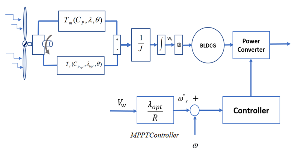
Fig. 2. Control system of wind energy
Figure 2 illustrates the procedure of the control algorithm intended for the mode of maximizing power (MPPT). The system's control comprises 3 separate loops that are responsible for controlling (maximizing the power point, field or vector, and the control of the wind turbine by means of an observer.
2. Simulation of wind turbine aerodynamics in Simulink
The turbine's output mechanical power is dependent on the speed.
Wind VW, is given in table [5].
Table
Output mechanical power of the wind turbine [5]
Wind speed Vw in m/s | Capacity kW |
1 | 0 |
2 | 0 |
3 | 0.25 |
4 | 0.5 |
5 | 1.5 |
6 | 2.5 |
7 | 4 |
8 | 6 |
9 | 8.6 |
10 | 11.8 |
11 | 15.6 |
12 | 20 |
13 | 20 |
14 | 20 |
15 | 20 |
We built a complex turbine system using MATLAB as shown in the figure below using the mathematical system as shown in the figure 3.
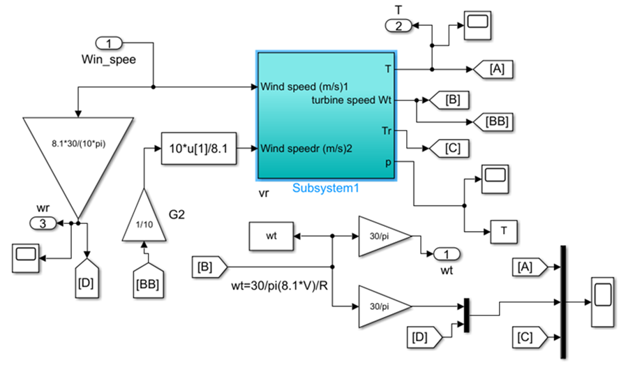
Fig. 3. Modelling system WECS By simulink
Visual representation of the mathematical model compiled in Simulink. Equations (1-5) were used when constructing the model. The modeling scheme of the wind turbine is shown in figure 4.
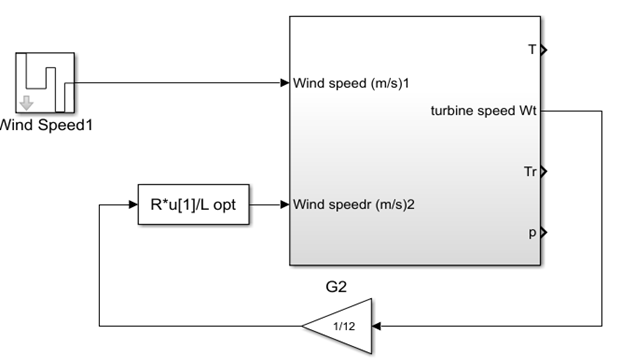
Fig. 4. Wind turbine simulation diagram in Simulink
The mathematical model for controlling the speed λ coefficient is shown in figure 5.
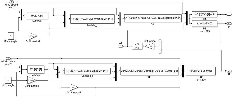
Fig. 5. Mathematical model of speed control
Take a sample of the wind speed as shown in the figure below, where it varies from 15 m/s to 5 m/s at different times shown in figure below (fig. 6).
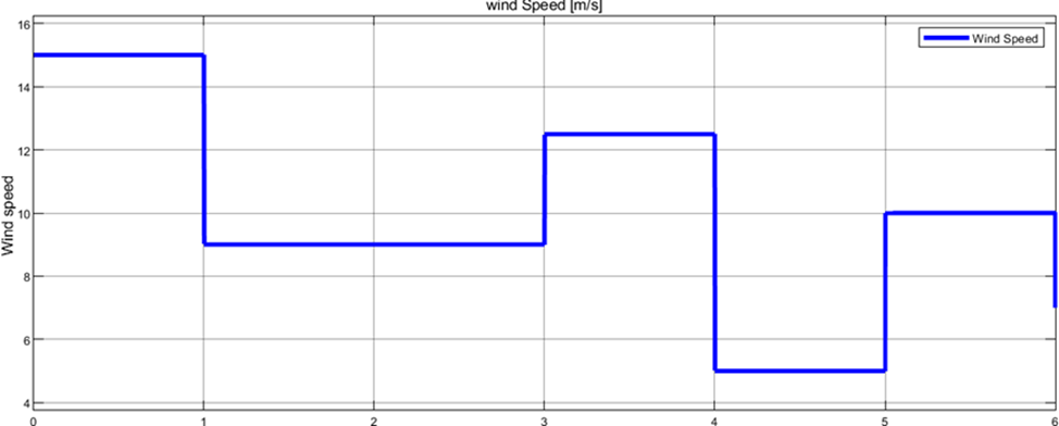
Fig. 6. Variable wind speed
We observe that the optimal turbine speed is different for different wind speeds, as illustrated in the figure below.
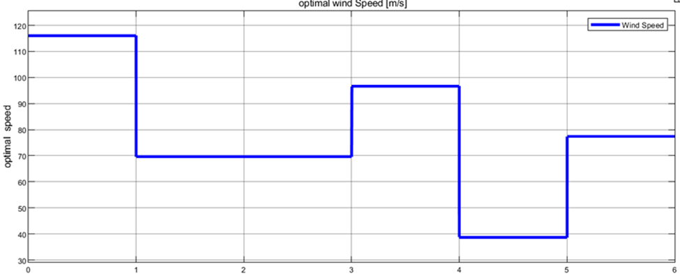
Fig. 7. Optimal turbine speed with time
We also notice the change in the actual speed depending on the change in wind speed, as in the figure below.
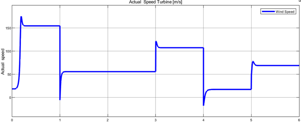
Fig. 8. Turbine speed with time
Here, the system that was developed using MATLAB is observed to correspond to the optimal speed while also matching the actual turbine speed and the optimal torque of the turbine, both of which indicate the overall response speed when wind speed is altered, the controller causes the system to correspond to the new wind speed, as in the figure below figure 9.
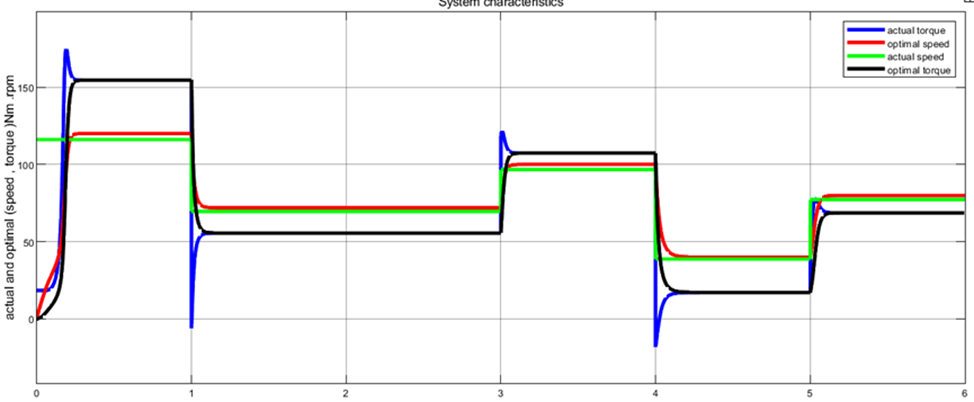
Fig. 9. Torque and speed with time
The mechanical and specific properties of wind turbines are a major concern for researchers, relying on the angle of attack and the blade. We will consider a range of different wind speeds, as shown in the figure below. We observed from mechanical properties experiments that the angle of attack has an impact on turbine power; the higher the angle, the lower the turbine power, and vice versa.
The wind energy utilization coefficient (Cp) value peaks at 0.48 when the blade angle of attack is β=0, over a range of β values from 0 to 50 degrees.
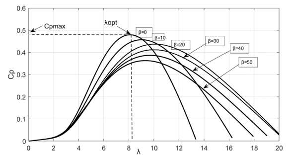
Fig. 10. Aerodynamic characteristics
Conclusion
This project aims to demonstrate the effectiveness of precise parameters based on a large generator and its behavior as a wind turbine to overcome the continuously changing nonlinear nature of wind. The paper also covers the basic principles of wind turbine system modeling, which were used to design and simulate the system's turbine. A mathematical model was developed to manage the aerodynamics of a vertical-axis wind turbine. A turbine that harnesses wind energy was modeled in Simulink. The effect of the blade's angle of attack on the turbine's speed was examined. The power of the turbine is derived from the speed, and the maximum efficiency of the turbine was achieved. The maximum efficiency is reached at a speed of 6, which implies that the turbine's circular motion should be approximately 20 rad/s. It can be said that the average wind speed and turbine speed will be less than the most effective values. As such, during the design of a wind generator, it's important to recognize the pattern of wasted energy during operation.
